
Hitachi

Overview

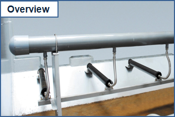
This cylindrical device suits various air diffuser layouts.
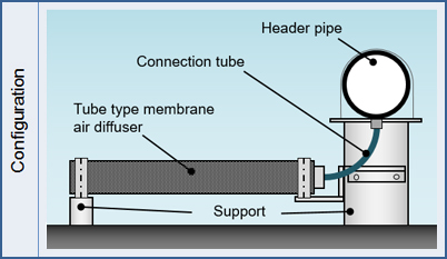
Configuration

Configuration
Element size Φ93×1000mm
Bubbling area 930cm2
Aeration volume 40~400L/min/membrane
Membrane EPDM
Support SUS304 or SS400(Painted)
Connection tube SUS304
Header pipe FRP

In the case of HMD-T10S standard element.

Features

  1. Pressure loss
    • Low pressure loss
      Comparison of pressure loss

      Comparison of pressure loss
      Pressure loss Ceramic plate Tube membrane
      Initial Approx. 2kPa Approx. 4kPa
      Aging Max. 8kPa Max. 3kPa
      Total Max. 10kPa > Max. 7kPa

      Comparison of pressure loss

      Compared to a ceramic plate type, the aging pressure loss of the tube membrane type is lower, although the initial pressure loss is slightly higher.
      Therefore, an operation period equal to or longer than that of a ceramic plate type is possible.
    • Small change of pressure loss


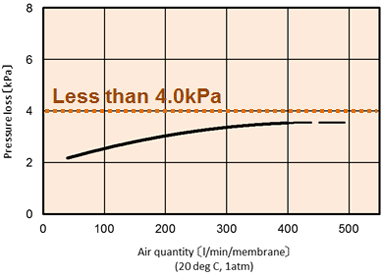
      Change of pressure loss

      (In the case of HMD-T10S standard element.)

      Since the change of pressure loss is low with respect to the change of the air volume, it is easy to control the air volume.
  2. Oxygen dissolution
    • High oxygen dissolution

      Dissolution efficiency can be about 25% because the bubble diameter becomes approx. 1mm due to a vibration effect that occurs when air passes through, even though the slit diameter for air passage is large (2mm).
    • Low oxygen dissolution drop rate


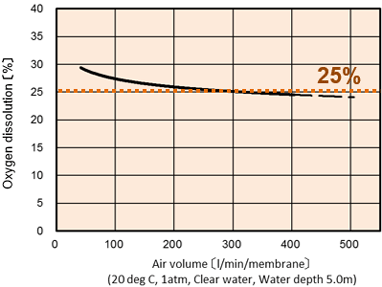
      Change of Oxygen Dissolution

      The oxygen dissolution drop rate after long-term operation is approx. 10%, while that of a ceramic plate type is approx. 25%.
    • Small oxygen dissolution efficiency decline
      Since the oxygen dissolution efficiency decline is small with respect to the change of the air volume, it is easy to control the air volume.
    (In the case of HMD-T10S standard element.)
  3. No operating restrictions
    • The ceramic type membrane has many operating restrictions because of the increase of pressure loss due to the occurrence of biofilm during operation with a small volume or when operation is stopped.
    • In the case of the tube membrane type, air passes through the slits and an adverse current of wastewater is prevented by water pressure when operation is stopped, so no operating restrictions are required.

    During Operation


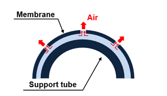
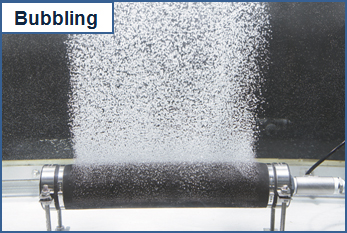
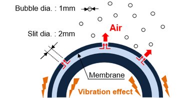
    Air passes only through the slits (2mm).

    When Stopped


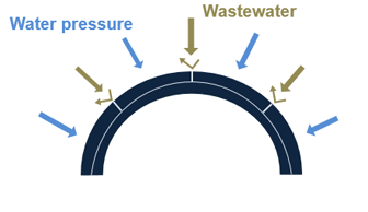
    Membrane adheres to the support tube by water pressure.
    →Adverse tide is prevented.

  4. Applicable to various tank shapes
    • It is easy to ensure the swirl flow velocity because the Tube Membrane Type Air Diffuser is not easily affected by the water flow.
    • For this reason, the Tube Membrane Type Air Diffuser is applicable for various tank shapes.

    Example: Application with standard activated sludge method


    Regular aerobic tank
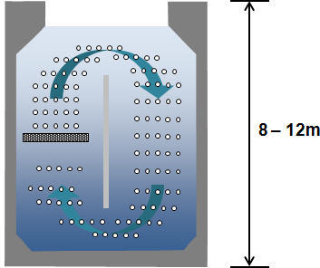

    Deep aerobic tank

Application

Applications Number of installation sites Total number of membranes
Sewage treatment 11 8,297
MBR* 1 128
For rural communities 14 532
Septic tanks 1 100
Sludge carbonization 1 152

Many installations have been completed in Japan.

*
MBR : Membrane Bio Reactor.