Interest in energy-saving and reusable energy has been growing since the Great East Japan Earthquake, and methods of safely guiding passengers during emergencies when the power supply from power companies fails have become an area of concern. Hitachi has responded by focusing on a stationary energy storage system with an emergency train travel function. During a power failure, the stationary energy storage system uses power stored in lithium-ion batteries to enable trains to travel to the nearest station under their own power with the passengers still on board. The stationary energy storage system’s emergency train travel function was studied and developed through discussions with Tokyo Metro Co., Ltd. The stationary energy storage system was considered for operation at the Kasai substation on the Tokyo Metro Tozai Line, and after field testing there, was recently delivered for service at that site.

Power Supply Systems Department, Transportation Systems Division, Railway Systems Business Unit, Hitachi, Ltd. He is currently engaged in system engineering for railway electrical conversion systems.

Power Electronics Design Department, Industrial Products Business Unit, Hitachi, Ltd. He is currently engaged in the development of regenerative power storage systems.

Power Electronics Design Department, Industrial Products Business Unit, Hitachi, Ltd. He is currently engaged in the development of power electronics products.
SINCE delivery of the first lithium-ion battery-driven stationary energy storage system by Hitachi in 2007, ten stationary energy storage systems have been put into operation around the world. The stationary energy storage system was developed as a regenerative power system with an energy-saving function that prevents regeneration cancelled, which can cause regenerative braking failure in trains, and supplies power stored in lithium-ion batteries as energy for powering. However, the stationary energy storage system does not only prevent regeneration cancelled, it also has been studied for applications that involve using its power supply function to supplement substation power or for train travel. In 2014, Hitachi field-tested a train powered entirely by lithium-ion batteries, and verified the feasibility of using lithium-ion batteries for emergency train travel(1).
Given this background, this article reports on the creation of a self-sufficient power system and a function for switching to emergency travel mode, which were required for the full-scale implementation of the stationary energy storage system, along with improvements to the direct current (DC) to DC converter for charge/discharge control.
The stationary energy storage system uses lithium-ion batteries to store regenerative power generated from the braking force of a train, and supplies this stored power while powering. The system is designed to use power effectively by repeating this series of operations.
The stationary energy storage system is connected to the feeder line (positive side) and rail (negative side) in a substation via a DC high-speed circuit breaker (HSCB) panel and isolator panel (see Fig. 1). The DC HSCB panel is designed to break the circuit to the feeder line on the positive side, and the isolator panel is designed to break the circuit to the rail on the negative side. The stationary energy storage system is composed of a chopper panel (DC-DC converter) and storage battery panel. The chopper panel is used to perform the appropriate charge/discharge control operations in response to the storage battery state and feeding state.
Fig. 1—Stationary Energy Storage System Configuration. The figure shows the configuration of the system with the stationary energy storage system in the center.
Configuring the stationary energy storage system required choosing storage batteries with enough performance to keep up with sharply rising regenerative power spikes. Since the batteries would be used as substation equipment, they also needed to withstand prolonged operation and repeated charging and discharging. The lithium-ion batteries used in hybrid electric vehicles (HEVs) were selected since they had an established track record and proven reliability (see Fig. 2). As storage media, HEV lithium-ion batteries have relatively high energy density and output density (see Fig. 3). Information about the internal states of the stationary energy storage system's lithium-ion batteries, such as cell voltage and battery temperature, is sent to the chopper panel via the battery controller unit (BCU). The results are used to apply the proper control operations to the storage batteries, extending their life(2).
Fig. 2—Exterior of the Lithium-ion Battery Module. The stationary energy storage system uses the same lithium-ion batteries used in hybrid cars.
Fig. 3—Ability Distribution Map of Various Storage Battery Elements.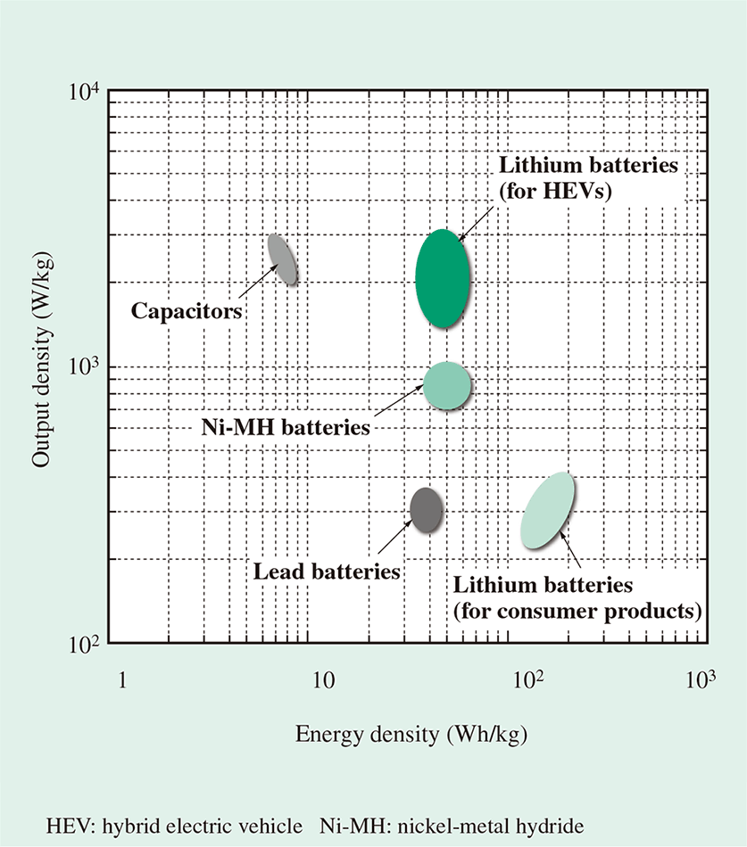 The distribution map shows a comparison of the abilities of the major storage battery media.
The chopper panel's DC-DC converter is a buck-boost chopper driven by an insulated-gate bipolar transistor (IGBT). The proper IGBT would usually be determined based on the feeding voltage, but it was felt that using the same IGBT for every feeding voltage could enable a standardized structure. For a DC 1,500 V feeding voltage, a general-purpose DC 1.7 kV-class IGBT was used by setting three chopper levels, enabling the same standardized structure used for a DC 750 V feeding voltage. The previous switching frequency was doubled to 1,200 Hz (for 50 Hz zones), seeking to reduce the size and noise of the storage battery DC reactor. Also, an air-cooled converter and DC reactor was used, reducing the chopper panel's footprint by 30% compared with Hitachi's conventional model.
The stationary energy storage systems currently in operation run in energy-saving mode or regeneration cancelled prevention mode. The latest stationary energy storage system has a new emergency travel mode that lets trains run on storage battery power alone when a major power failure shuts off the power supply from the power company to the substation. When the feeding voltage drops or goes to zero, the stationary energy storage system detects an input voltage drop, temporarily stops the train and enters standby. An emergency travel instruction is then sent to the stationary energy storage system from outside if it is determined that the feeding voltage drop was caused by a shutoff in the power supply from the power company, requiring emergency train travel. When the stationary energy storage system receives an emergency travel mode signal, it switches the following functions to the settings used for emergency travel.
TABLE 1. Auxiliary Power Supply Panel Main Specifications
 The table lists the main specifications of the auxiliary power supply panel, which provides the self-sufficient power supply function for auxiliary devices.
When the emergency travel instruction described above is sent to the train, it is presumed that a substation power failure will occur due to the shutdown in power transmission from the power company. In this event, it is necessary to assume also that power will not be supplied to auxiliary devices such as control systems or fans. For that reason, an auxiliary power supply panel that provides a self-sufficient power supply function for auxiliary devices was installed as an option for stationary energy storage systems that have the emergency travel function.
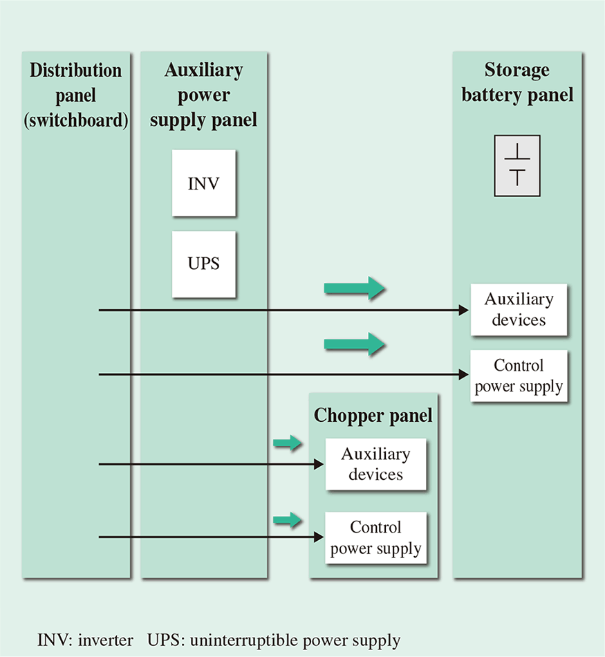
During normal operation, the stationary energy storage system receives the auxiliary device power supply from the substation's distribution panel (switchboard). But, when the emergency travel mode signal is received, the lithium-ion battery power is supplied to the stationary energy storage system via the inverter and uninterruptible power supply (UPS) in the auxiliary power supply panel (see Fig. 4 and Fig. 5).
Fig. 6 shows the exterior of the auxiliary power supply panel, and Table 1 lists its main specifications.
Fig. 4—Flow of Control Power Supply/Auxiliary Device Power Supply during Normal Train Travel.
 The figure shows the flow of the control power/auxiliary device power normally supplied to the chopper panel and storage battery panel.
Fig. 5—Flow of Control Power Supply/Auxiliary Device Power Supply during Emergency Travel Mode.
 The figure shows the flow of the control power/auxiliary device power supplied to the chopper panel and storage battery panel during emergency travel mode.
Fig. 6—Chopper Panel (with Auxiliary Power Supply Panel at Far Right).
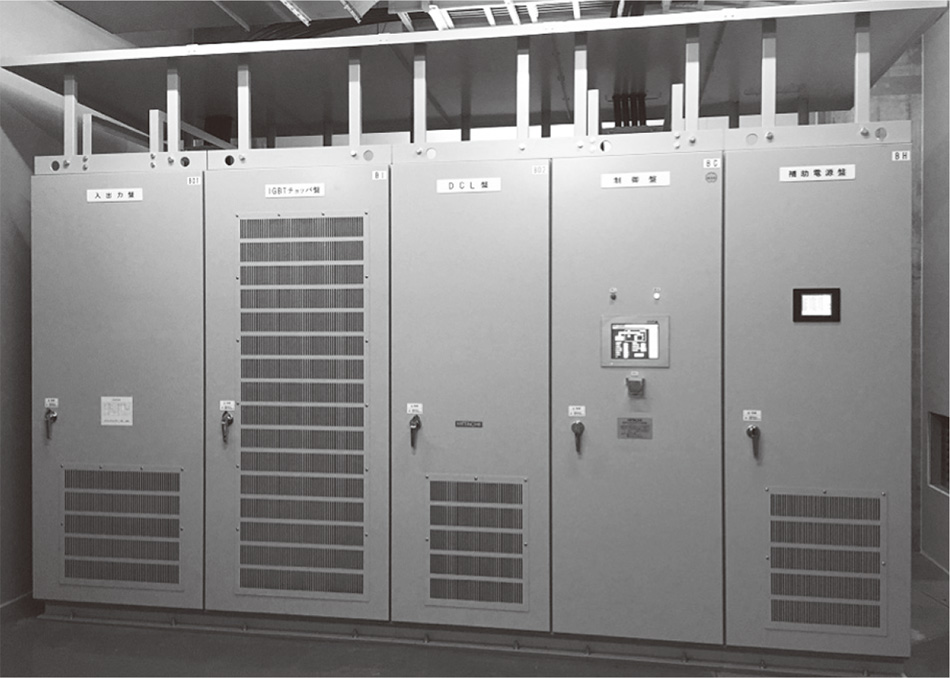 The photo shows the chopper panel and the auxiliary power supply panel, which provides the self-sufficient power supply function for auxiliary devices.
The final system specifications were set by considering factors such as the field test results and the self-sufficient power supply function for auxiliary devices. Table 2 shows a comparison of the specifications at the time of field testing and at the time of delivery.
TABLE 2. Comparison of Main Specifications during Field Test and in Delivered Product
 The table compares the stationary energy storage system's main specifications when it was field-tested and when it was delivered.
After being equipped with an improved chopper panel and auxiliary power supply panel, a stationary energy storage system with an emergency travel function was delivered to the Kasai substation of the Tokyo Metro Tozai Line, where it was field tested in February 2016. It started operation in March 2016 after further onsite testing, such as inductive interference tests. So, alongside the previous energy-saving and regeneration cancelled prevention functions, the new emergency travel function has now been added to the stationary energy storage system product lineup.
But there are still challenges to overcome for future stationary energy storage system operation, such as:
In addition to overcoming the challenges discussed in the previous chapter, Hitachi intends to continue working on meeting the demands for improving stationary energy storage system functions, refining the stationary energy storage system into a convenient system for use in saving energy, and safely guiding and protecting rail passengers.
