Many commuter trains in the 200-km/h range use AC electric railcars. The need to outfit these railcars with traction transformers limits the availability of underfloor space compared to DC railcars. Miniaturization is essential for short train sets in particular where outfitting space is limited. Accordingly, with the aim of reducing equipment size, Hitachi has developed a system that uses liquid cooling to cool power semiconductor devices. This article introduces this system and describes the system’s integrated structure, which combines traction converters and auxiliary power supplies.

Rolling Stock Electrical Systems Design Department, Mito Rail Systems Product Division, Railway Systems Business Unit, Hitachi, Ltd. He is currently engaged in the development of hardware for traction systems.
Rolling Stock Electrical Systems Design Department, Mito Rail Systems Product Division, Railway Systems Business Unit, Hitachi, Ltd. He is currently engaged in the development of traction systems.
Rolling Stock Electrical Systems Design Department, Mito Rail Systems Product Division, Railway Systems Business Unit, Hitachi, Ltd. He is currently engaged in the development of hardware for traction systems.
Home Appliances Research Department, Center for Technology Innovation – Mechanical Engineering, Research & Development Group, Hitachi, Ltd. He is currently engaged in the research and development of cooling technology for semiconductor power devices. Mr. Yasuda is a member of The Japan Society of Mechanical Engineers (JSME), and is a certified P.E.Jp (Professional Engineer, Japan) of Mechanical Engineering.
Rolling Stock Electrical Systems Design Department, Mito Rail Systems Product Division, Railway Systems Business Unit, Hitachi, Ltd. He is currently engaged in the development of traction systems.
WHEREAS the traction converter and auxiliary power supply in rolling stock usually constitute separate units in Japan, compact units that combine the traction converter and auxiliary power supply into one unit are more common in the European market. Recognizing this, Hitachi set about developing an integrated traction converter and auxiliary power supply unit that combines traction converters with auxiliary power supplies as a way to reduce size, weight, and cost.
This development included the adoption of a liquid cooling system, which is often used in Europe, in order to improve the cooling efficiency of the cooling system for the power semiconductor devices and to enable the equipment to be housed in a high-density package. Fig. 1 shows a comparison of the configurations for forced air cooling and liquid cooling. Because a liquid cooling system uses the circulation of coolant to efficiently carry heat away from the semiconductor devices, it provides more freedom for equipment layout than the forced air cooling used in the past and reduces unused space. The objective here was to improve cooling efficiency, to reduce the space occupied by cooling system components, and to make the equipment smaller. However, it is difficult to achieve an equipment volume and weight that have competitive power in the global marketplace by just adopting a liquid cooling system. To achieve this, Hitachi adopted a traction circuit configuration suitable for integrating traction converters and auxiliary power supplies, and went about reducing the number of components and making the unit smaller. Hitachi also looked at how the power unit for the liquid cooling system could be mounted to minimize the amount of space needed for inspection. The overall equipment size was also reduced by integrating the control logic units used for the traction converters and auxiliary power supplies (previously housed as separate units).
This article describes the benefits of the reduction in size made possible by adopting a liquid cooling system and the traction circuit configuration that enabled a reduction in the number of components.
Fig. 1—Comparison of Configurations for Forced Air Cooling and Liquid Cooling.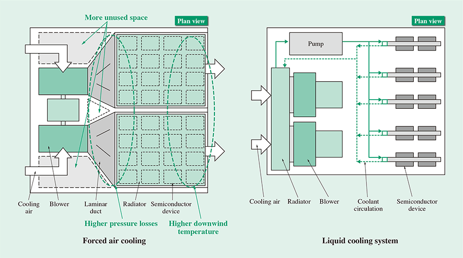 A problem with forced air cooling is that it requires larger blowers to cope with the higher pressure losses due to the presence of the laminar ducts. Equipment volume is also larger due to the greater amount of unused space.
Fig. 2—Configuration of Liquid Cooling System.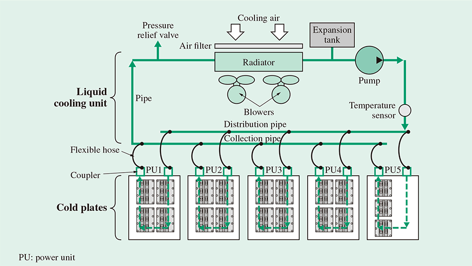 The system is designed to have fewer components and to balance the temperatures of each power unit by constructing the system to cool the semiconductor devices of five power units all at once, in one cooling system.
Fig. 3—Exterior of a Cold Plate and a Liquid Cooling Unit.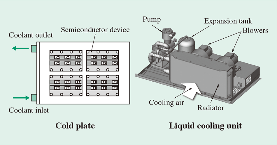 The liquid cooling system is made up of multiple cold plates that draw heat from the semiconductor devices and a cooling unit that supplies coolant to the cold plates and that dissipates the heat carried by the coolant to the outside air.
Fig. 2 shows the specific configuration of the liquid cooling system. The system is made up of multiple cold plates that draw heat from the semiconductor devices and a cooling unit that supplies coolant to the cold plates and that dissipates the heat carried by the coolant to the outside air. Fig. 3 shows diagrams of these components.
The system must be able to support a configuration consisting of two control systems controlling two motors each in order to provide the redundancy to cope with equipment faults, even when operating on short train sets of only two or three cars. For this reason, the system for the traction circuit attaches four semiconductor modules to each side of the converter or inverter cold plates based on the number of semiconductor devices, with the semiconductor devices being mounted on both sides due to dimensional constraints. For the auxiliary power supply, meanwhile, because the amperage is lower than that in the converters and inverters, 2-in-1 semiconductor devices in modules containing upper and lower circuit arms are mounted on both sides, with three modules on each side. This means there are a total of five cold plates: two for the converters, two for the inverters, and one for the auxiliary power supply.
Fig. 4—Benefits of the Liquid Cooling System.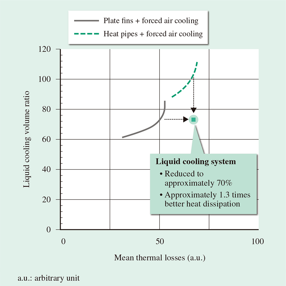 The larger the mean thermal losses in the flow path, the more beneficial it is to use a liquid cooling system in terms of the volume of the cooling system.
Fig. 4 shows the benefits of using the liquid cooling system. The cooling system volume in the graph represents the total volume of components used for semiconductor device cooling, including blowers and radiators. The graph is a plot of the cooling system volume required by each cooling method to deal with different levels of thermal losses, expressed as a proportion of the volume of the existing cooling system. The graph shows that the volume of the new liquid cooling system is approximately 70% of that required by a system that uses heat pipes and forced air cooling to deal with the same level of thermal losses, and that the new system's cooling capacity is approximately 1.3 times that of a system that uses plate fins and forced air cooling.
Fig. 5 shows a breakdown of the reduction in cooling system volume. The new liquid cooling system reduces the volume of the blowers and radiators to 69% by integrating them into the liquid cooling unit. Similarly, replacing unused space with flexible hose has reduced the volume of this part to 78%. The result is a cooling system that is reduced to approximately 70% by volume.
Fig. 5—Breakdown of Reductions in System Volume from Using the Liquid Cooling Unit.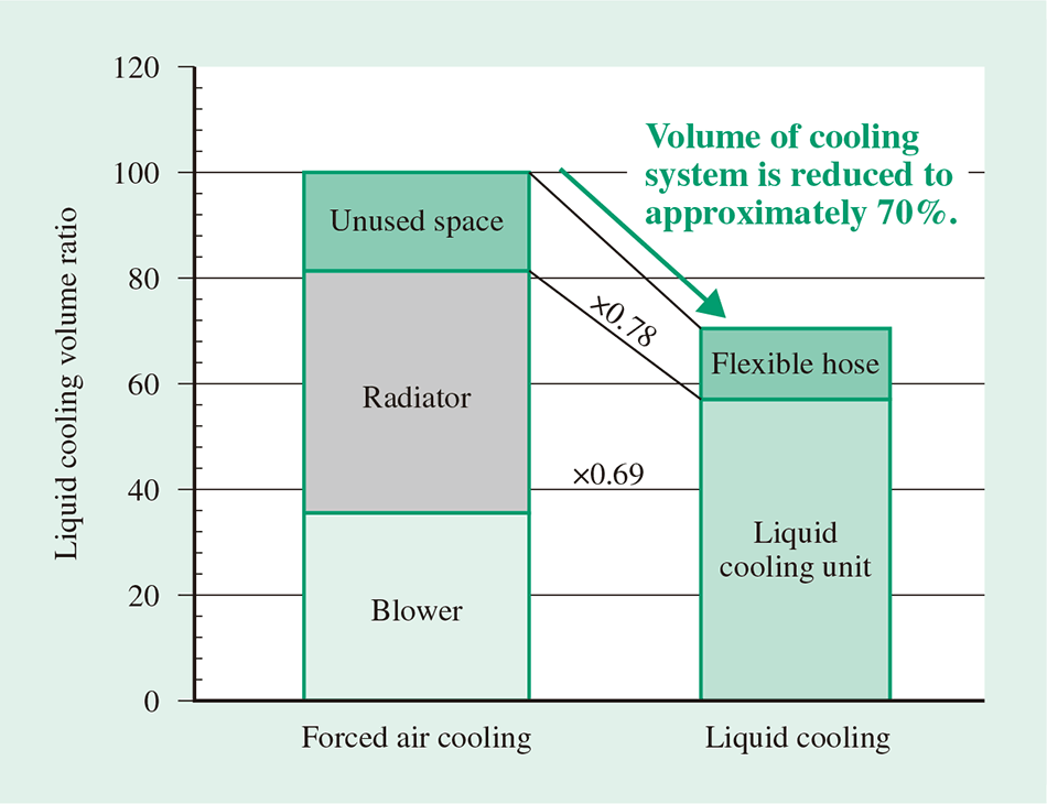 The volume of the new cooling system is reduced to approximately 70% of a forced air cooling system.
Fig. 6—Power Unit Housing.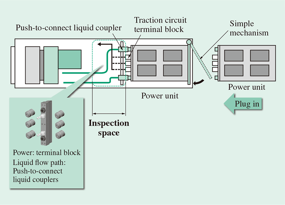 Eliminating the need to incorporate cooling components such as aluminium fins or heat pipes means that each power unit can be made about 50% lighter than with forced air cooling, and is easier to install and remove.
Fig. 6 shows a side view of the power unit housing. Push-to-connect liquid couplers are used for the liquid flow path interface, with a simple mechanism for plugging in and holding the couplers in place. Terminal blocks are used for the traction circuit connections. Because inserting or removing the power unit brings the liquid flow path with it, this design is easier to replace and provides space for inspection while also making the equipment smaller and reducing its cost.
Fig. 7 shows the traction circuit system. The 25-kV/50-Hz alternating current (AC) power supply from the pantograph is input to the converter and inverter power units via the vacuum circuit-breaker, traction transformer, vacuum contactor, charging contactor, and charging resistor. This system controls each bogie separately (two control systems that control two motors each) in order to provide the redundancy to cope with equipment faults, even when operating on short train sets of only two or three cars.
The semiconductor devices in the power units can be implemented with 3.3-kV/800-A or 3.3-kV/1,200-A insulated-gate bipolar transistors (IGBTs), using either type depending on the required control capacity. The units use two-level, snubber-less, single-phase voltage pulse width modulation (PWM) converters and two-level, snubber-less, three-phase voltage PWM inverters, and achieve enhanced reliability by reducing the number of components.
The system is equipped with a small-capacity brake chopper to ensure that braking continues without a discontinuity, even when the railcars pass from one section to another during regenerative braking. This absorbs the regenerative power and maintains the braking force by routing the power generated during braking to the brake resistor rather than the pantograph.
In the auxiliary power supply, the inverter circuit is connected to the direct current (DC) stage of each traction converter circuit to reduce inductance by minimizing the amount of wiring from the traction converter to the auxiliary power supply circuit, thereby eliminating the need for the smoothing reactor used in the past to suppress current fluctuations. The number of components has also been reduced by eliminating the charging resistor, unit switch, and discharging resistor, which were required when the circuit was implemented with separate units.
Connecting the inverter circuit of the auxiliary power supply to the DC stage means that the auxiliary power supply can avoid a temporary power outage by using the electric power generated by the brake if the pantograph voltage is lost when passing from one section to another.
Fig. 7—Traction Circuit Systems. The number of components was reduced by connecting an auxiliary power supply inverter circuit to the DC stage of each of the traction circuits.
Whereas separate control logic units were used for the traction circuits and auxiliary power supplies in the past, the new design has saved space by eliminating circuit boards that perform duplicate functions, combining the analogue input boards and gate boards, and consolidating the circuit board racks. Moreover, having dual traction circuits and dual auxiliary power supply circuits provides redundancy as it means there are also two control logic units.
The layout of the system is divided into the integrated traction converter and auxiliary power supply units on one hand, and the transformer box on the other (see Fig. 8 and Fig. 9).
Each integrated traction converter and auxiliary power supply unit contains two vacuum contactors, two converter power units, and two inverter power units; a single auxiliary power supply unit that is used for both; a liquid cooling unit for each of the power units; and the control logic units that control these.
The transformer box contains an inverter transformer for the auxiliary power supply circuit, a battery charging circuit, and an electromagnetic contactor.
Fig. 8—Exterior of the Integrated Traction Converter and Auxiliary Power Supply.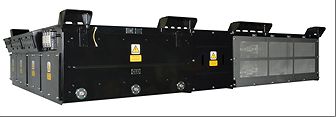 Use of a liquid cooling system enabled the traction converter and auxiliary power supply to be integrated and made smaller. Depending on the customer requirements, the system can be configured as two units that drive two motors each or as one unit that drives four motors.
Fig. 9—Exterior of the Transformer Box. The transformer box is provided as a separate unit to deal with varied customer requirements for things like capacity, supply voltage, and frequency.
This article has presented an overview of the integrated traction converter and auxiliary power supply unit and described the liquid cooling and electrical systems developed by Hitachi.
The system has been fitted in Hitachi's standard AT-200 commuter trains, the first of which were supplied to Scotland in the UK (as the Class 385) (see Fig. 10). In the future, Hitachi expects the system to satisfy diverse requirements for rolling stock in markets throughout the world.
Fig. 10—Image of the AT-200.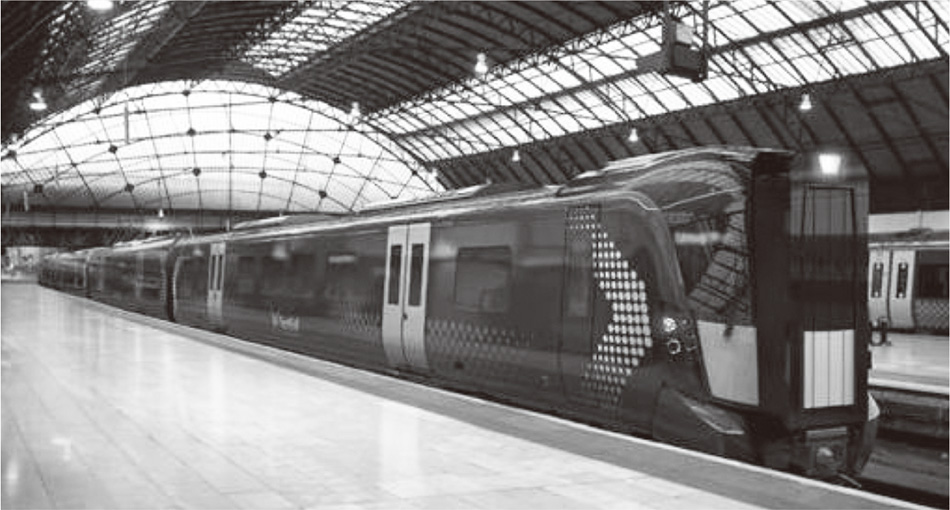 The new system will be fitted in Hitachi’s standard AT-200 commuter trains.
