It has been almost 200 years since electromagnetic induction was discovered. Motors and transformers that employ this principle were the Hitachi's founding products, and these businesses have been inherited by Hitachi Industrial Equipment Systems Co., Ltd. and the Industrial Products Business Unit of Hitachi, Ltd. Since the 1960s, equipment such as motors and transformers, and the pumps, fans, and air compressors that utilize them, were developed into the core industrial products that support electric power and energy, industry and distribution, water and sewerage, cities, public transportation, and other parts of modern life with the modernization of Japan’s public infrastructure. In the 2000s, efforts have been made to reduce the carbon footprints of these products. In the fields of electric power and industry in particular, development has focused on achieving increased energy savings and higher efficiency, and environmentally conscious products have been proposed that comply with the Top Runner Program standards and International Electrotechnical Commission standards. This paper describes these products and technologies that are supported by the comprehensive strengths of Hitachi.
Motor & Control Equipment Design Department, Drive Systems Division, Business Operations Group, Hitachi Industrial Equipment Systems Co., Ltd. Current work and research: Design and development of induction motors.

Development Center, Drive Systems Division, Business Operations Group, Hitachi Industrial Equipment Systems Co., Ltd. Current work and research: Design and development of PM synchronous motors.
Pump & Fan Turbo-Machinery Design Department, Drive Systems Division, Business Operations Group, Hitachi Industrial Equipment Systems Co., Ltd. Current work and research: Design and development of pumps and water supply units.
Development Center, Drive Systems Division, Business Operations Group, Hitachi Industrial Equipment Systems Co., Ltd. Current work and research: Design and development of controllers for PM synchronous motors.
Motor Systems Research Department, Center for Technology Innovation – Controls, Research & Development Group, Hitachi, Ltd. Current work and research: Performance improvement for industrial motor systems. Society memberships: Institute of Electrical Engineers of Japan (IEEJ).
Motor Systems Research Department, Center for Technology Innovation – Controls, Research & Development Group, Hitachi, Ltd. Current work and research: Development of Electrical Machinery. Society memberships: IEEJ.
Electrical Machinery Design Department, Electrical Machinery Production Division, Industrial Products Business Unit, Hitachi, Ltd. Current work and research: Development of Electrical Machinery. Society memberships: The Japan Society of Mechanical Engineers, Atomic Energy Society of Japan, Cryogenics and Superconductivity Society of Japan.
Motor Systems Research Department, Center for Technology Innovation – Controls, Research & Development Group, Hitachi, Ltd. Current work and research: Development of Electrical Machinery. Society memberships: Institute of Electrical Engineers of Japan.

Pump & Fan Development Group, Pump & Fan Division, Machinery Systems Division, Industrial Products Business Unit Hitachi, Ltd. Current work and research: Development of evaluation method of rotor stability for high-pressure multistage pumps and application of stabilizing technology. Society memberships: Turbomachinery Society of Japan.

Pump & Fan Development Group, Pump & Fan Division, Machinery Systems Division, Industrial Products Business Unit Hitachi, Ltd. Current work and research: Development of evaluation method of rotor stability for high-pressure multistage pumps and application of stabilizing technology. Society memberships: Turbomachinery Society of Japan.
Pump & Fan Development Group, Pump & Fan Division, Machinery Systems Division, Industrial Products Business Unit Hitachi, Ltd. Current work and research: Development and design of high-pressure multistage pumps. Society memberships: Turbomachinery Society of Japan.
Department of Mechanical Engineering, National Defense Academy. Current work and research: Consultant for Hitachi, Ltd. Society memberships: Turbomachinery Society of Japan, The Japan Society of Mechanical Engineers.
Hitachi began operating as a business focused on electric motors with the development of a 5-hp (3.7-kW) motor in 1910. From then until now, motors and products that use them have been the core industrial products of Hitachi and have played a big role in the wide-ranging Social Innovation Business that has been advanced by Hitachi.
During this time, Hitachi has made industrial motors lighter and more compact by improving materials and manufacturing methods. Now, the weight of Hitachi's 5-hp motors is approximately one-fourth of that when the company was established. Hitachi 1,000- to 8,500-kW high-voltage motors also use a modular design, and products where the weight has been reduced by 30% by further revising the rotor structure and cooling structure have been released. Reducing the size of equipment contributes to saving resources because it reduces the amount of materials used, and reducing the weight is also effective for reducing the amount of carbon emissions due to transportation.
Since 2000, the development of industrial motors, which are the core products for saving energy and reducing carbon emissions, has also been advancing rapidly with the goal of increasing efficiency. The total electric energy consumption in Japan is approximately 1 trillion kWh, and around 55% of this is accounted for by equipment that uses motors. Looking at the industry segment, 75% is accounted for by the electric power use of motors. Therefore, if the efficiency of industrial motors could be improved by 1%, then power generation could be reduced by around a single 1-MW-class power plant.
Hitachi Industrial Equipment Systems Co., Ltd. has developed high-efficiency motors using iron-based amorphous alloy ribbon in collaboration with Research & Development Group, Hitachi, Ltd. Motor efficiency standards are described according to the International Energy Efficiency Code (IE) defined by the International Electrotechnical Commission. The motors most recently developed by Hitachi meet the IE5 standard, which is being developed as the highest level. Revolutionary materials are needed in order to increase efficiency, and moreover, new manufacturing methods for applying these materials are essential for increasing reliability.
While every country around the world is competing to improve the efficiency of motors, they have also been working to improve the efficiency of systems by using inverters. When inductions motors are used in fans and pumps, the typical usage method is to run the motor at a constant speed and control the air or water flow by opening and closing a damper or valve. This method uses a constant rotational speed where the motor rotates even while the damper or valve is closed. If an inverter is used, on the other hand, it is possible to implement control that gives the required rotation at the required time while keeping the damper or valve continuously open (or rendering it unnecessary). Given that the use of electric power decreases in proportion to the cube of rotational speed, this kind of variable speed system is expected to deliver large energy savings. The proportion of induction motors in Japan that have inverters installed is less than 30%, and there is still room for improvement. The scope of application is also planned to expand to air compressors in order to take environmental consciousness to the next level.
In the future, utility can be further increased by combining the motor, inverter, and mechanisms into a single unit. Hitachi Industrial Equipment Systems is manufacturing the HE pump, which combines a motor, inverter, and pump into a single unit. Conventionally, the motor and pump were integrated as a single unit but the inverter was installed in a control box, but with the HE pump, the control box and the wiring work from the box to the motor can be reduced and reliability can be improved.
To operate industrial equipment appropriately and stably while maintaining reliability, it is essential to have technology for measuring and diagnosing the operational state. In particular, stable operation of electric power plants is necessary in order to protect the environment. There is a trend for the large pumps and fans that are used in electric power plants to have longer operation periods and longer maintenance cycles. Thus, equipment maintenance methods are undergoing a transition from time-based maintenance (TBM) to condition based-maintenance (CBM). Hitachi is developing a method for estimating the state of deterioration due to aging of the internal components of boiler feed water pump (BFP) in thermal power plants without disassembly. Hitachi is working to expand social and industrial innovation through its comprehensive strengths in providing smart industrial products that use this kind of method.
Figure 1 — Comparison of Motor Efficiency (4 Poles, 50 Hz)
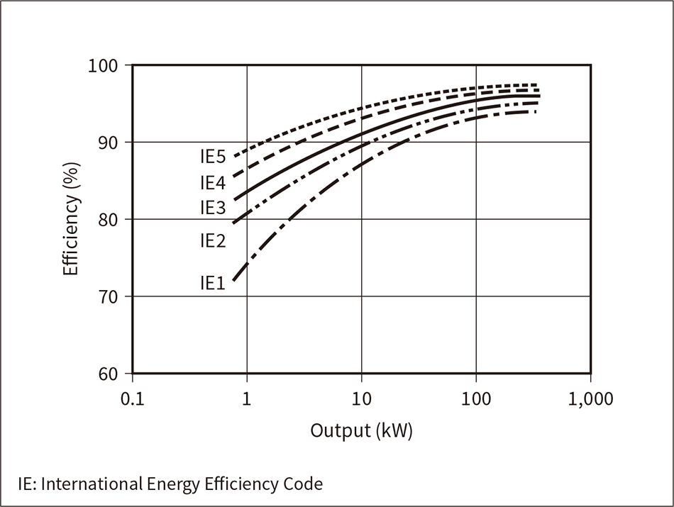 This graph shows a comparison of motor efficiencies from IE1 to IE5 (IE5 values are tentative). The efficiency values are standardized by motor output power.
Controlling and reducing energy consumption is an issue from the perspectives of conserving the global environment and preventing global warming, and various efforts are now under way. Electric power consumption by motors is thought to account for 40% to 50% of the total electric power consumption globally, and in Japan motors are estimated to account for approximately 55% of the total electric power consumption and approximately 75% of industrial electric power energy. Accordingly, increasing the efficiency of motors is expected to contribute greatly to increasing energy savings. Furthermore, the results of a survey on the use of motors in Japan show that common applications include pumps, compressors, air blowers, power transmission equipment, and machining tools and that the average annual operating time is around 4,000 h, the number of years used is 15 to 20 years, the load factor during operation is around 60%, and the inverter drive ratio is 10% to 20%. In other words, common characteristics include long use times, high load factors during operation, and constant speed operation. In light of these characteristics, three-phase induction motors have been designated as target equipment for the Top Runner system, which was introduced by the revised Energy Conservation Act. From FY2015 it became obligatory to ship motors that comply with the Top Runner standards. It is calculated that if all of the standard efficiency motors (IE1 motors) in use throughout Japan were replaced with Top Runner motors (IE3 motors), the reduction in energy consumption would be 15.5 billion kWh/year, which is equivalent to approximately 1.5% of Japan’s total power consumption. The corresponding reduction in CO2 emissions is calculated to be 8.6 billion kg-CO2/year (CO2 emissions factor: 0.554 kg-CO2/kWh). Figure 1 shows a comparison of the efficiency levels from IE1 to IE5 (IE5 values are tentative).
Figure 2 — Top Runner Motors
 This photograph shows an external view of the premium efficiency motor series, which achieves IE3 class efficiency while ensuring attachment compatibility with older motors.
Among its efforts in the area of high-efficiency motors, Hitachi Industrial Equipment Systems has developed a series of 0.75- to 300-kW motors, which comply with Top Runner standards, through optimized design by electromagnetic field analysis, optimization of cooling structures, and new design and revision of each part. In addition to ensuring installation compatibility with previous motors, these motors also provide an energy-saving effect, a higher grade of thermal resistance, increased reliability through international protection (IP) 55 for outdoor models, supported for a wider range of power supply specifications, and produced less noise. In addition, industry-leading low starting current and high torque was delivered while meeting efficiency standards by an optimized design of the electrical components including a newly introduced shape for the conventional rotor groove shape. Moving into the future, progress is being made investigating motors that support the IE4 class of even higher efficiency than the IE3 efficiency class in three-phase induction motors in order to achieve even high energy savings (see Figure 2).
Figure 3 — PM Synchronous Motor and Inverter
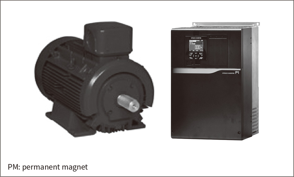 PM synchronous motors provide high-efficiency operation when combined with an inverter.
Pumps, compressors, blowers, and other equipment that are the main applications of motors can reduce power consumption by variable speed operation using an inverter to match the required workload. Given the background of a further need to increase energy savings, there is growing industrial use of permanent magnet (PM) synchronous motors that offer even higher efficiency than three-phase induction motors. Hitachi Industrial Equipment Systems has developed a 3.7- to 55-kW standard series of motors with efficiency equivalent to IE4 based on the design and manufacturing technology of PM synchronous motors that were previously developed specifically for pump and compressor applications, and began selling these motors in 2012. High-efficiency operation is made possible through combination with the magnetic pole position sensorless control from the Hitachi WJ200 and SJ700 general-purpose inverters (see Figure 3). These have previously been used such as in factory equipment and contribute to energy saving. In terms of ultra-high-efficiency motors, Hitachi is developing motors that exceed the IE5 class through increased motor efficiency by employing iron-based amorphous alloy ribbon in the iron cores of motors, reducing losses, and also employing a double-rotor type axial gap structure.
In the area of servo motors, which are one type of PM synchronous motor, Hitachi is creating servo systems for large presses and injection molding equipment to support the need to transition from hydraulics to electric power, and is creating products such as motors for thin gearless elevator equipment for special customers (see Figure 4).
Figure 4 — Large-capacity Servo Motors and Amplifier
 Servo motors are a type of PM synchronous motor. These are used in products such as large presses and injection molding equipment.
Figure 5 — Energy Saving Using PM Motors and Inverters
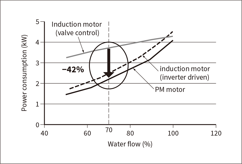 This graph shows an example of the relationship between pump water flow and power consumption. Power consumption can be reduced by 42% under conditions of 70% water flow when using a PM motor compared with an induction motor with valve control.
In the industrial fields of pumps and fans, efforts are being made toward developing energy-saving products to meet the need for energy savings that is growing every year. In the past, Hitachi Industrial Equipment Systems has met this demand by using high-efficiency induction motors and using variable speed control by introducing inverters. Conventionally, air and water equipment such as pumps and fans use an induction motor that runs at a fixed speed and adjust the flow rate (air volume) using a valve. However, this kind of generic valve control creates large losses in energy consumption due to the resistance of the valve. In contrast to this kind of valve control, the resistance component can be absorbed by variable speed control using an inverter drive. Yet, to install an inverter, a new control box also needs to be installed, and the installation costs of the control box in addition to the motor and inverter costs greatly increases the installation costs, making it difficult to use inverters with small-capacity equipment (particularly 7.5 kW and lower). In contrast, if the motor and inverter are built into a single unit for example, then this removes the need to install a control box but greatly increases the size, which breaks compatibility in terms of the external dimensions of the motor and attachment dimensions. This makes it difficult to replace existing equipment. Therefore, by using PM motors which offer the advantage of being much more compact than induction motors and utilizing the space that is made available from their compact size to combine the motor with an inverter in a single unit, it is possible to create dimensional compatibility with conventional induction motors and replace the motors in existing equipment without changing the equipment or installing a control box. This makes it possible to implement further energy saving easily in a regular inverter + induction motor unit (see Figure 5).
Based on this concept, a pump with a built-in controller-integrated PM motor [product name: HE pump (motor capacity: 1.5 kW to 7.5 kW)] has been developed.
Figures 6 and 7 show the external view and structure of the controller-integrated PM motor. The controller unit comprises a primary circuit board with an inverter, converter, and control block; a smoothing capacitor; a direct current (DC) reactor; a power supply input board with noise filter; and an interface board. The main circuit board is stored inside a dedicated aluminum controller case, and a cooling fan is installed at the planar end of the molded housing. The smoothing capacitor is separate from the main circuit board and is stored in a dedicated plastic capacitor case that is attached to the housing. The DC reactor is stored in a dedicated steel plate DC reactor box that is attached to the planar end of the housing separate from the main circuit board. The power supply input board is equipped with a noise filter and is housed in the terminal box together with the interface board. To support standalone outdoor installation, the motor has a waterproof structure where the terminal box and DC reactor box are sealed inside by a rubber gasket seated between the case and lid. The main circuit board and capacitor are stored in a lidless case located on the outside of the motor; therefore, waterproofing, humidity proofing, and condensation countermeasures are implemented by sealing the whole outer casing in resin. Furthermore, the main circuit board and power supply input board with noise filter have been given enhanced vibration resistance and shock resistance by sealing and fixing them within resin. Each of the component located around the outer circumference of the motor is connected via power and communication cables that are wired and connected to inside the DC reactor box and main circuit board. The connections inside the main circuit board are connected on the outside. Therefore, waterproofing is implemented by using waterproof crimping sleeves and waterproof connectors; an end cover, splash-proof cover, and outer cover are installed that enclose the outer circumference of the motor and controller; and the motor and controller are cooled by forming a wind tunnel structure and using an external door fan on the motor. The outer cover blocks direct sunlight to prevent deterioration of plastic parts located inside the cover, and a sound-absorbing material is attached to the inside of the outer cover to suppress noise such as the high-frequency noise that occurs due to the controller carrier and the wind noise of the fan.
The HE pump offers a 55% reduction in power consumption compared with motors released before the motor efficiency standards (motor efficiency class IE1), and a large energy-saving effect can be obtained by upgrading to the HE pump (see Figure 8).
Figure 6 — External View of a Typical Controller-integrated PM Motor
 Dimensional compatibility with conventional induction motor is achieved by integrating an inverter into the space secured by using a PM motor that is more compact than the induction motor.
Figure 7 — Structural Diagram of a Typical PM Motor with Integrated Controller
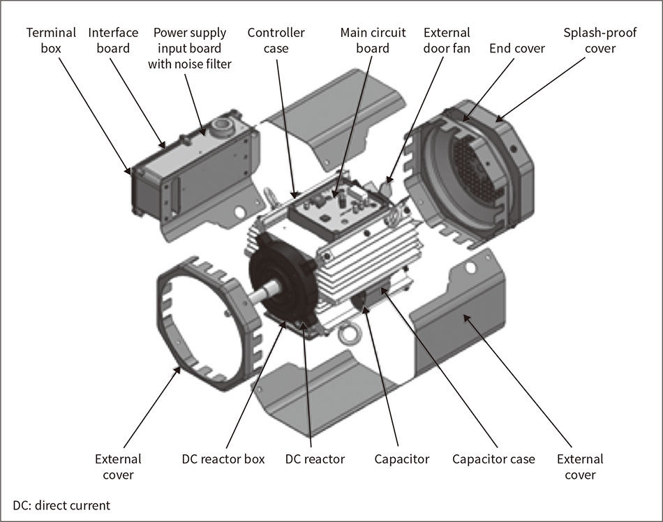 This shows the arrangement of the main parts. To support standalone outdoor installation, waterproofing, humidity proofing, and condensation countermeasures have been implemented; vibration resistance and shock resistance have been enhanced; and deterioration of plastic parts has been suppressed.
Figure 8 — Comparison of Power Consumption
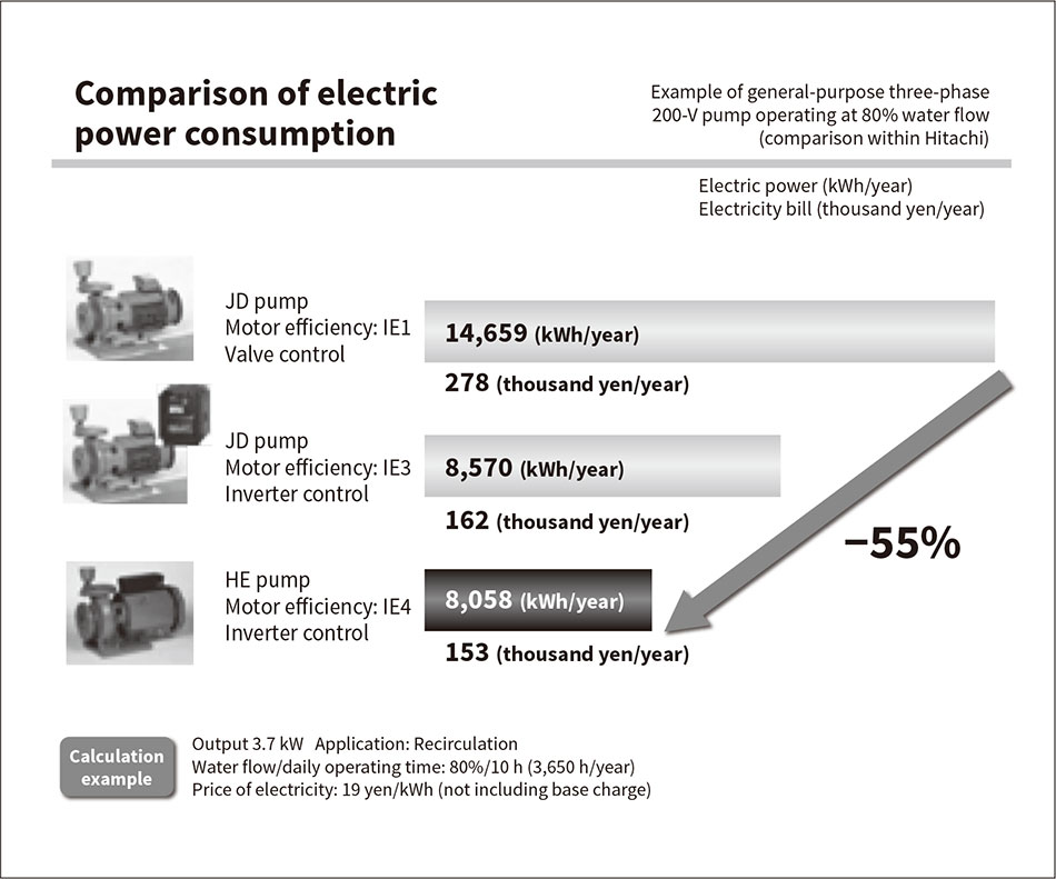 This figure shows a comparison of power consumption and electricity bills between the HE pump and previous products. Power consumption can be reduced by approximately 55% compared to the motor before the high efficiency standards.
In addition to constant speed operation using valve control, the pump market has demanded the capability of changing the number of operating pumps depending on the level of water demand with alternating or parallel operation that switches between alternating operation of one pump and parallel operation of two pumps, as well as a small-water-flow stop function that saves energy by stopping the pump during small water flow. These kinds of advanced function specifications that were conventionally implemented using a control box are realized in product proposals with minimal configuration by adding a dedicated circuit board inside the controller-integrated PM motor.
Because of the demand for even more compactness and higher efficiency in order to reduce the energy consumption of motors from the perspective of environmental concerns, customer demand for smaller, lighter motors that maintain the same level of performance as before is also increasing for the general industrial motors that drive a wide variety of equipment. Against this background, the development of a new motor series for general industry was started with the goal of delivering a 30% reduction in weight over previous models. Table 1 shows the main specifications and Figure 9 shows the external appearance.
For this series, development was pursued focusing on an analysis-driven detailed investigation in order to implement a modular design and the concepts shown below (see Figure 10).
Table 1 — Specifications of the New Motor Series for General Industry
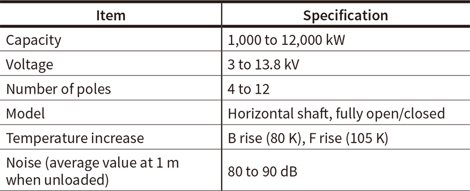 This table lists the main specifications of this series.
Figure 9 — New Motor Series for General Industry
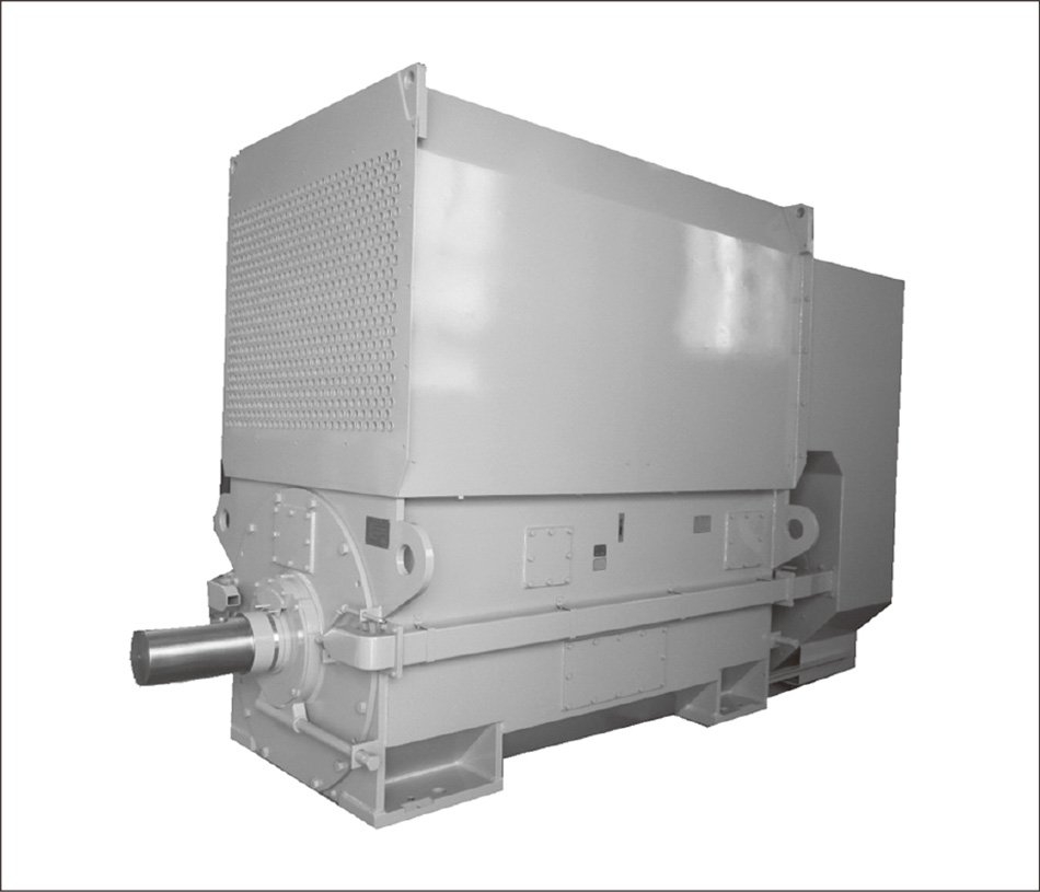 This shows an external view of a motor in this series developed based on the concept of high cooling, compactness, and light weight.
Figure 10 — Development Concepts of the New Motor Series for General Industry
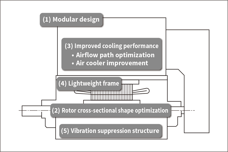 Investigation of the development parameters proactively utilized analyses such as electromagnetic field, heat flow, structure optimization, and vibrations.
In recent years, there has been a trend toward extending equipment operation periods and maintenance intervals in order to improve the utilization ratio of plants. To extend the operating hours of plants, there is also a continuing migration in the equipment maintenance methods from conventional TBM to CBM.
In thermal power plants, there is a large amount of equipment in operation, among which the BFP is one of the most important pieces of auxiliary equipment in the water supply system. Because the BFP rotates at high speed (approximately 6,000 min-1), if the internal components of the pump become aged due to excessive continuous operation, the vibration may grow suddenly (unstable vibrations may occur). For the power plant to operate stably and to ensure reliability over long periods, it is important to have technology for appropriately understanding and managing the state of the equipment.
This section introduces a method of applying and measuring vibrations as a technology for diagnosing vibrations in the BFP during steady-state operation and estimate the internal aging condition without disassembling the pump.
The BFP that supplies hot high-pressure water to the boiler is a horizontal-shaft multistage pump consisting of multiple impellers arranged in series (see Figure 11). The rotor is supported by bearings at both ends, and multiple annular seals (in fine gaps) are fitted between the rotor and stator in order to prevent reduced efficiency of the pump due to leaks. The annular seals affect the rotor as submerged bearings, so it is necessary to investigate the effects of the annular seals on vibrations when designing the pump.
High-speed pumps such as BFPs exhibit large changes in vibration characteristics depending on their rotational speed (see Figure 12). BFPs are generally operated at rotational speeds between the critical speed N1 of the rotor and the onset (threshold) of instability N2 (the rotational speed at which unstable vibrations occur), but in this kind of pump, the annular seals become more worn and the gap becomes larger when operated for a long period of time. Consequently, the effectiveness as a bearing changes and the onset of instability moves to lower speeds. When the onset of instability is less than the operating speed, unstable vibrations occur that affect pump operation.
Although BFP vibrations are continuously monitored in almost all plants using an attached instrument, the nature of the vibrations that are emitted changes above the onset of instability, so it is difficult to predict when the onset of instability is approaching the operating speed by monitoring vibration trends.
Figure 11 — Example Structure of BFP
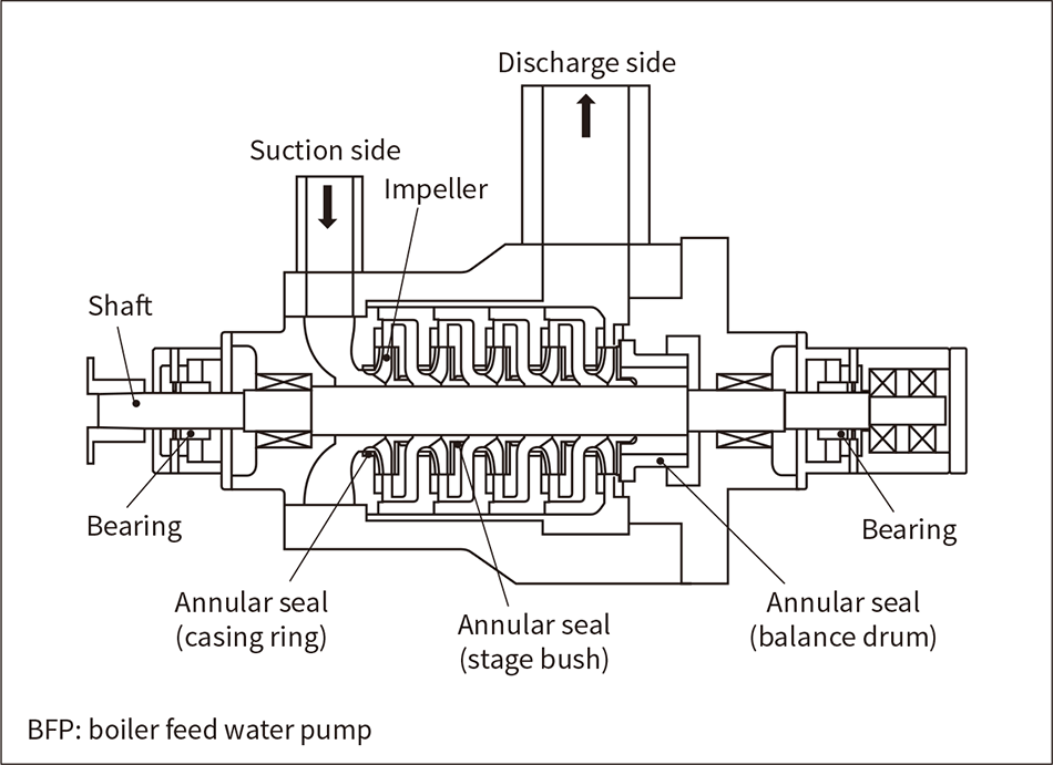 The annular seals in the fine gaps have a bearing effect, so investigation is needed of the effect of annular seals on vibration.
Figure 12 — Variation in Onset of Instability with a Worn Annular Seal
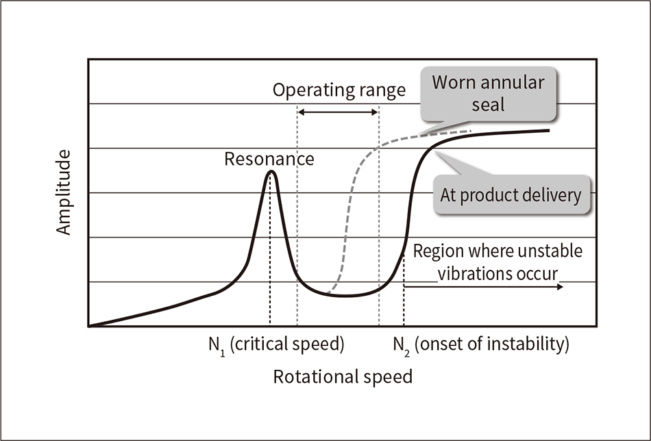 BFPs operate between the critical speed N1 and onset of instability N2. Abrasion of the annular seal due to aging deterioration decreases the onset of instability, and this causes the onset of instability N2 to enter the operating range and then unstable vibrations occur.
Figure 13 — Excitation Application and Measurement System
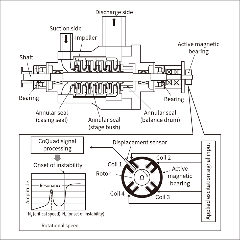 Excitation is applied to the rotor during operation by an active magnetic bearing, and the onset of instability is predicted by CoQuad signal processing of the detected vibration waveform.
The circumstances of aging deterioration of pumps in each plant differ depending on the pump usage conditions. For this reason, Hitachi has developed a method of applying and measuring vibrations by using an active magnetic bearing with the aim of predicting unstable vibrations before they occur.
This technology predicts the onset of instability by applying a very small excitation to the rotor during operation using an active magnetic bearing, performing CoQuad (separation of real and imaginary parts) signal processing on the detected vibration waveform, and determining the stability of the rotor by using conditional equations obtained from the equations of motion using the Bently-Muszynska λ model. This method is able to determine the onset of instability, which cannot be evaluated by normal monitoring of vibration trends, and makes it possible to estimate the progress of aging deterioration inside the pump (wear of the annular seals).
This excitation diagnosis technology comprises an active magnetic bearing, an applied excitation signal input system, and a CoQuad signal processing system (see Figure 13). The active magnetic bearing is fitted to the end of the pump shaft; therefore, diagnosis of not only new pumps but also existing pumps can be handled by additional fitting, for example, using an attachment. In the future, development will pursue applications in field diagnosis technology to make it possible to propose the optimal maintenance intervals to customers.
This paper described technology for reducing the environmental impact of motors and increasing the reliability of motors and products that use them.
Since its founding, Hitachi has focused its resources on its Social Innovation Business in various forms. After developing a 5-hp motor in 1910, Hitachi developed businesses that are essential to electric power generation, transportation, and industry, and manufactured a large electric locomotive in 1924. In the 1930s, these technological capabilities expanded to include equipment such as transformers, elevators, refrigerators, and large-scale electrolyzers. Subsequently, Hitachi revolutionized the lifestyles of the Japanese people by focusing on rail solutions such as the Tokyo Monorail and Tokaido Shinkansen (bullet train). In the 1980s, Hitachi pursued social and industrial innovation such as digital communications, medical equipment, water and sewage management, thermal power, environmental equipment, nuclear power, and motor vehicles based on its accumulated results.
In recent years, the development of the Internet of Things, in which everything is connected to the Internet, has been anticipated. The motors and applied products introduced in this paper are powerful core industrial products that can use networks and the cloud by integration with controllers and communication devices. On this basis, Hitachi is planning to further expand social and industrial innovation using its comprehensive ability to provide smart industrial products that are able to perform functions such as monitoring of equipment operation states and predictive diagnostics.
In the 21st century, Hitachi is aiming to contribute to the development of infrastructure overseas and to become a major global player by developing new technologies such as new energy grids, big data processing, wireless communications, and the cloud in addition to the social and industrial infrastructure technology that Hitachi has already cultivated in Japan.
