Solutions Based on Measurement Technology
As even small amounts of corrosion in the electronic components used in control equipment for social infrastructure can be a cause of faults, appropriate anti-corrosion measures are needed to ensure reliable long-term operation. One useful indicator for anti-corrosion measures is to assess the corrosivity of the environment where the equipment is installed. With objectives that include assessing the environment prior to installation, performing monitoring once the equipment enters use, and determining the environment when a fault occurs, Hitachi has developed a visual inspection corrosion sensor for visualizing reduced sulfur gas species or the corrosivity of the environment, and an electrical resistance corrosion sensor suitable for long-term measurement. These corrosion sensors serve as key devices for accurate environmental assessment through analysis of changes over time and of the atmosphere where the equipment is installed.


The potential impact on the public and business of service outages caused by faults in electric power, industrial facilities, transportation, or other parts of the social infrastructure makes it important that facilities and their control equipment be kept operating reliably. Moreover, because this infrastructure is frequently located in corrosive environments, it is common practice to put anti-corrosion measures in place. Unfortunately, one of the factors behind new corrosion risks is when infrastructure is installed in locations where it has rarely been installed in the past. Among the effective measures for ensuring that control equipment continues to function reliably under such conditions are those based on the environment and on the choice of materials, involving the rapid measurement and assessment of the site environment, the installation of systems for improving the environment, and the use of components that are resistant to corrosion. Given that environmental measurement and assessment are often constrained by remoteness and other geographical factors, and by the customer's circumstances, there has been a demand for corrosion sensing solutions that are also suitable for the above situations.
With the aim of assessing environments that are corrosive due to the presence of sulfides, a frequent cause of faults in the electronics used in social infrastructure(1), Hitachi has developed a visual inspection corrosion sensor that, without requiring any special skills to use, can provide a visual indication of the gas species at a site and assess the corrosivity of the environment (an indication of how much electronic devices in that environment will be subject to corrosion). Making use of the principle of this visual inspection corrosion sensor, Hitachi has also developed an electrical resistance corrosion sensor that provides continuous long-term monitoring of corrosivity.
The visual inspection corrosion sensor allows us, just by reading its two corrosion indicators without any special equipment or skills, to identify reduced sulfur gas (sulfur-based gases that are a cause of sulfide corrosion) species and corrosivity of an environment with corrosion indicator (CI)-1 (black) and CI-2 (yellow), respectively (see Figure 1).
The visual inspection corrosion sensor is made up of a transparent substrate plated with silver thin film on one side and a channel through which the gas can enter. When the silver thin film is viewed though the transparent substrate after it has been corroded by the reduced sulfur gases which diffuse inside this channel, those regions of the silver thin film which are partially corroded in thickness direction appear blacker than the initial silver color, while those regions where the gases have corroded all the way through to the interface of the transparent substrate turn yellow. Utilizing the fact that the degree of transparency and reflectiveness of the silver thin film depends on its thickness, this thickness is chosen such that these two different color changes will occur.
The corrosion of the silver thin film visualized by the corrosion indicators is the result of: (a) the diffusion of reduced sulfur gases [e.g. hydrogen sulfide (H2S) and elemental sulfur (S8)], and (b) the reaction between the silver and the reduced sulfur gases (see Figure 2). The elongation of the corrosion indicators depends not only on the concentration of the gas but also on its properties (diffusion coefficient and corrosion reaction probability with silver), the shape of the channel through which the gas enters, and the thickness of the silver thin film. The more easily the gas diffuses through air, the greater the corroded region of the silver thin film is. Accordingly, the length of the black region, which is not influenced by the gas concentration and does not change with time, is used as a corrosion indicator (CI-1) to identify the reduced sulfur gas. Similarly, the length of the yellow region, which elongates over time depending on the concentration of reduced sulfur gas in the environment, is used as a corrosion indicator (CI-2) to indicate how corrosive the environment is. Environmental testing and corrosion simulation were utilized in designing the shape of the sensor channel, with two separate designs produced for short-duration and standard measurements respectively. This allows the sensor to assess the environment in a variety of different areas.
Figure 1—Visual Inspection Corrosion Sensor (Top) and Principle of Measurement (Bottom) The corrosion indicators that make up the visual inspection corrosion sensor are exposed to the environment. Corrosion indicator CI-1 identifies reduced sulfur gas species and corrosion indicator CI-2 assesses how corrosive the environment is.
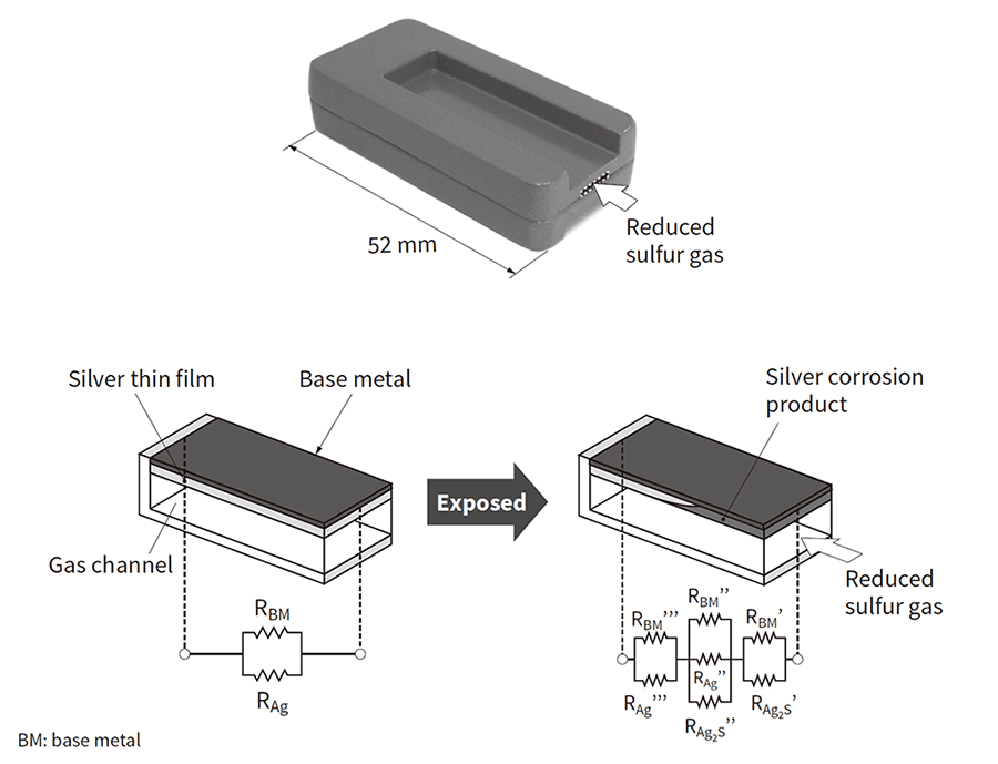
Figure 3—Exterior of Electrical Resistance Corrosion Sensor (Top) and Principle of Measurement (Bottom) The corrosivity of the environment is determined by measuring electrical resistance due to the corrosion of the silver thin film, which is a sensor electrode.
In place of the corrosion indicators used by the visual inspection corrosion sensor, the electrical resistance corrosion sensor assesses the corrosivity of an environment by measuring electrical resistance due to the corrosion in a sensor electrode (silver thin film) (see Figure 3). The sensor is made up of a substrate plated with base metal (BM) wiring and silver thin film on one side and a channel through which the gas can enter. The initial electrical resistance is a combined resistance of the BM wiring and the silver thin film while the electrical resistance is, as part of the silver thin film is turned into silver sulfide, a combined resistance of the BM wiring, the silver-sulfide thin film and the silver thin film. By quantifying the relationship between the change in the electrical resistance and corrosivity before and after exposure, the environment's corrosivity can be assessed from the change in the electrical resistance.
As in the visual inspection corrosion sensor, the silver thin film in the gas channel of the electrical resistance corrosion sensor corrodes progressively in the longitudinal direction, starting from the edge. Accordingly, there is no reason in principle why the corrosion products should build up and peel off if the sensor is placed in a harsh environment or left out for a long time, and it has been demonstrated in practice that it can remain reliable over long periods. Also, because the sensor can be connected to existing instruments, it can be managed centrally on the cloud along with various other measurement data.
In an environment where control equipment is installed, the measurements from a corrosion sensor will vary depending on the duration and location of the measurement. Along with using a single corrosion sensor to assess the installment environment, it is also possible to carry out more detailed assessments by using several sensors to perform environmental space analysis and time analysis of weather data.
The corrosivity of an environment varies depending on where air conditioning and ventilation fans are located. This variation can be determined by using visual inspection corrosion sensors to perform measurements at several locations simultaneously. Since the visual inspection corrosion sensors can visualize an environment's corrosivity, these sensors are effective for comparing several locations' environments and identifying gas species as well as their sources (see Figure 4). On-site assessments can also be done using an environmental assessment app on a digital device. Likewise, the environments in remote locations can be visualized if on-site staff send photographs they have taken via mail.
When visual inspection corrosion sensors were left exposed for a month in the electrical room of a wastewater treatment plant, the CI-1 corrosion indicators indicated the presence of hydrogen sulfide, especially in locations near the intake ducts and doors, while the CI-2 corrosion indicators identified where the environment was highly corrosive (in need of environmental improvements or other measures). In contrast, as a filter is installed inside the control equipment, no presence of hydrogen sulfide could be seen while the CI-2 corrosion indicators indicated that a very low level of corrosivity in this location was maintained.
Figure 4—Conceptual Diagram of Environmental Space Assessment with Visual Inspection Corrosion Sensor (Left) and Example Use at Wastewater Plant (Right) Placing a number of visual inspection corrosion sensors at different locations makes it easy to identify gas species and where they are coming from. IC1 to IC5 are corrosivity classifications specified in the ISO 11844-1 standard(2), with higher numbers indicating harsher environments.
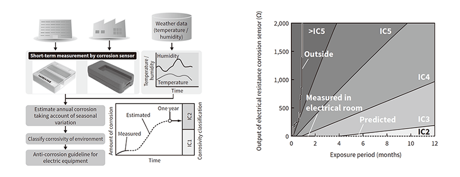
The corrosivity of an environment varies over time as well as space. It is possible to estimate how much corrosion occurs annually, taking account of seasonal variations, by combining data measured by a corrosion sensor over a short period (one to three months) with temperature and relative humidity figures obtained from public weather data (see Figure 5). The collected data is managed in the cloud and an environmental assessment application based on estimates of annual corrosion is provided via a portal for making use of the data.
In one example, the corrosivity of an environment was assessed using the electrical resistance from electrical resistance corrosion sensors left exposed for two months outside a petrochemical plant and in its control equipment room (see Figure 5). The outside environment was classified as highly corrosive (i.e. environmental improvements, etc. are necessary since reliability is affected). On the other hand, the control equipment room was designated as maintaining a low corrosive environment based on an estimated result in consideration of seasonal variations. A time-series analysis method is effective for short measurement periods or low corrosive environments.
Figure 5—Conceptual Diagram of Time-series Assessment with Corrosion Sensor (Left) and Example Use at Petrochemical Plant (Right) Annual corrosion can be estimated by combining short-term data measured by a corrosion sensor with temperature and relative humidity figures obtained from public weather data.
The progress of globalization is providing more and more opportunities for parts procurement, equipment assembly and installation, etc. in foreign countries, especially emerging countries and regions. It is forecasted that emissions of corrosive gases in emerging countries and regions are on the rise whereas the trend in Europe, America, and Japan is flat or falling(3). To ensure the stable operation of equipment, it is vital to control the occurrence of corrosive damage by knowing the environmental conditions during the storage and transportation of parts and products along with their operational environments. While visual inspection corrosion sensors, which are capable of visualizing environments, are useful for assessing storage and transportation environments, electrical resistance corrosion sensors, which can carry out long-term measurements, are useful for monitoring conditions.
The electrical resistance corrosion sensor can also be used as a hydrogen sulfide sensor by utilizing its ability to perform measurements in harsh environments over long periods of time. Concrete structures, for example, are subject to degradation due to hydrogen sulfide and this creates a demand for continuous monitoring of H2S levels that can serve as indicators of such degradation. If the relationship between H2S concentration and the amount of corrosion measured by the electrical resistance corrosion sensor can be obtained, the sensor can then be used for the measurement of H2S levels in the environment.
Corrosion damage to the control equipment used in social infrastructure occurs infrequently. However, when it occurs, it is expensive and time-consuming to identify its cause and take action. It has been reported that the cost of dealing with corrosion, including anti-corrosion design, accounts for a few percent of the sales income from electronic equipment(4). Measures based on past experience are essential for preventing corrosion damage in terms of both the environment and materials. In cases such as locations where equipment has not previously been used, or where climate change has taken place, however, there is a need to review measures that are predicated on past experience with new and existing equipment. Hitachi intends to proceed with the development of corrosion sensing solutions in which corrosion sensors serve as key devices, and that can assess how corrosive the environment is for all sorts of electronics, including the control equipment used in social infrastructure.