Interest in the use of streetcar-based mass-transit systems has grown amid the rising demand for environmentally friendly public transportation. Hitachi Rail S.p.A. has developed a new OBESS that can be retrofitted to existing streetcars with traditional overhead catenary systems to enable catenary-free operation. This upgrade allows streetcars to travel across sections of their route that lack overhead catenaries, as are commonly found in historic city centers, thereby improving both environmental performance and street appearance. This article describes the energy storage system and on-board BMS that enable catenary-free operation, and the DC-DC converter used to interface the new OBESS to the existing traction and auxiliary converters.


The rising demand for public transportation and the associated requirements for energy efficiency, pollution reduction, and lower capital cost make light rail (streetcars or trams) an attractive and competitive option for large and crowded metropolitan areas. Unfortunately, the overhead contact lines that supply these streetcars with electric power are an impediment to adoption, having a negative impact on both the environment and street aesthetics. In situations where environmental constraints are predominant, especially in historic city centers, the requirement for overhead catenary lines and power poles adds costs and poses problems for construction.
In response, Hitachi Rail S.p.A. has developed an on-board energy storage system (OBESS) that features efficient operation and enables streetcars to travel across sections of their route that lack catenaries. This means that streetcar routes can include large squares, historic city centers, or other areas of cultural interest without the need to install power poles to support overhead catenary lines, thereby avoiding the architectural issues and the detrimental effects on street appearance of such ugly infrastructure. Catenary-free operation also avoids adverse environmental impacts.
Hitachi Rail S.p.A. developed the OBESS with a standalone configuration that allows conventional catenary-supplied streetcars to be converted to hybrid operation (the ability to run without the presence of the catenary). Benefits include the business opportunities opened up by upgrading existing rolling stock to run on new routes and the option of removing unattractive catenary and power pole infrastructure from city centers.
The retrofitting of an OBESS to an existing vehicle needs to be done in a way that does not excessively increase the vehicle weight, that is easy to install, and that does not require modifications to the traction system that might invalidate homologation (regulatory approvals). What is required is a modular system that can satisfy different vehicle energy requirements and fit in the space available.
The features of the Hitachi Rail S.p.A.’s solution are as follows:
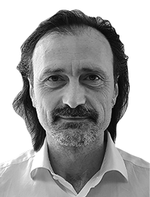
Fig. 1—Configuration of OBESS Installed on Car Roof with DC-DC Converter
 A complete OBESS is able to be installed using the space available on the roof of the vehicle. The extra weight this adds is not enough to require new homologation.
The OBESS (incorporating the ESU and BTMS) and DC-DC converter have been designed for installation on the vehicle roof, with the design replicating the exiting component layout as much as possible to make this easier. Both are housed in stainless steel, with the frames being physically attached to the sides of the vehicle by means of riveted brackets. For ease of installation, the electrical interface to the vehicle uses plug-in connectors for both high- and low-voltage circuits. Figure 1 shows an OBESS and DC-DC installed on a streetcar roof.
The buck-boost (step-up/step-down) DC-DC converter is used to convert between the different voltages of the OBESS and the main power line and traction system. The bidirectional converter features high-efficiency semiconductors and a high switching frequency to minimize both output voltage ripple and inductor size. The DC-DC converter is used for:
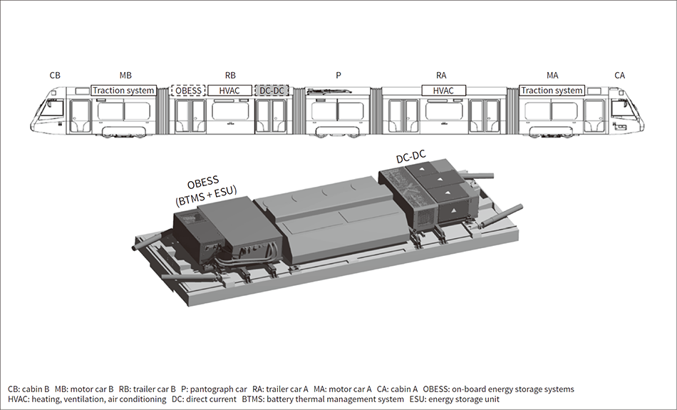
Fig. 2—Energy Flows Managed by DCCU
 The system is able to evaluate the energy required from the battery system and the energy available from the line, and manages the energy flows accordingly.
In all functional modes, the output voltage and current of the DC-DC converter are regulated by the duty cycle of each single-phase leg. During charging and discharging, the control system communicates with the ESU battery management system (BMS) to limit battery charging or discharging based on the battery’s state of charge (SoC) and whether the system is powering or regenerating (under traction or braking). This is done to keep the SoC within a suitable range, maximize use of regenerative energy by avoiding use of brakes, and maximize the supply of electric power from the battery to the traction system.
During recharging, the DC-DC converter steps down the DC link voltage to supply the desired output current for charging the ESU.
When under traction, the DC-DC converter steps up the voltage from the ESU to provide a constant voltage for powering all the vehicle subsystems, including the drive system.
The DC-DC converter control unit (DCCU) is able to interface with the vehicle network using the existing communication bus, whether it be Ethernet, Multifunction Vehicle Bus (MVB), or CAN.
The DCCU includes a power management module that specifies the charging or discharging power reference for the DC-DC converter based on information from the BMS and the available power feed. Figure 2 shows the energy flows managed by the DCCU in the different functional modes.
When power is supplied from a catenary, the ESU performs smart charging, meaning that the DCCU draws a surplus of energy from the network and uses it to charge the batteries, taking into account both the SoC and the traction energy requirement, and also ensuring that the maximum line current able to be drawn by the streetcar is not exceeded.
The Figure 3 shows the trip diagram for a streetcar traveling along a mixed line (with catenary and non-catenary zones) and Figure 4 shows an enlargement of a catenary zone where the ESU recharges the battery.
Fig. 3—Trip Diagram on Mixed Line
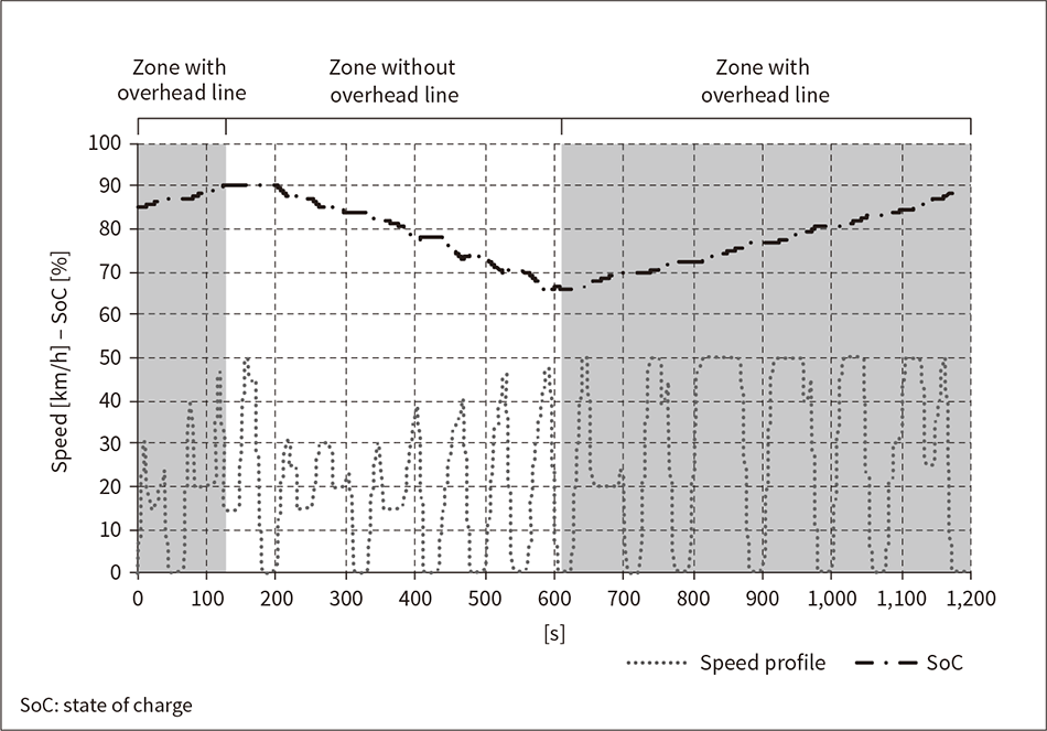 The diagram plots the speed and SoC along a testing route that includes zones with and without an overhead line.
Fig. 4—Trip Diagram when ESU Recharging from Overhead Line
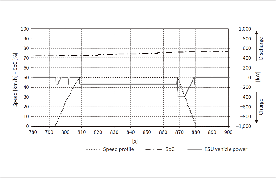 The figure shows an enlargement of the Figure 3 diagram for a zone with an overhead line. Power is drawn from the overhead line to recharge the battery system while the streetcar is coasting at constant speed.
The first step of ESU development is battery cell selection. The requirements for the battery pack are that it provide adequate energy storage capacity while also having a high cycling performance and high safety and reliability. Lithium-ion batteries are able to meet these requirements. Furthermore, a modular approach was adopted with each battery module being made up of 32 cells in an eight series/four parallel (8S4P) configuration. Figure 5 shows a photograph of the battery array and Table 1 lists the module’s main characteristics.
Table 1—Battery Module Characteristics

Fig. 5—Photograph of Battery Module Prototype
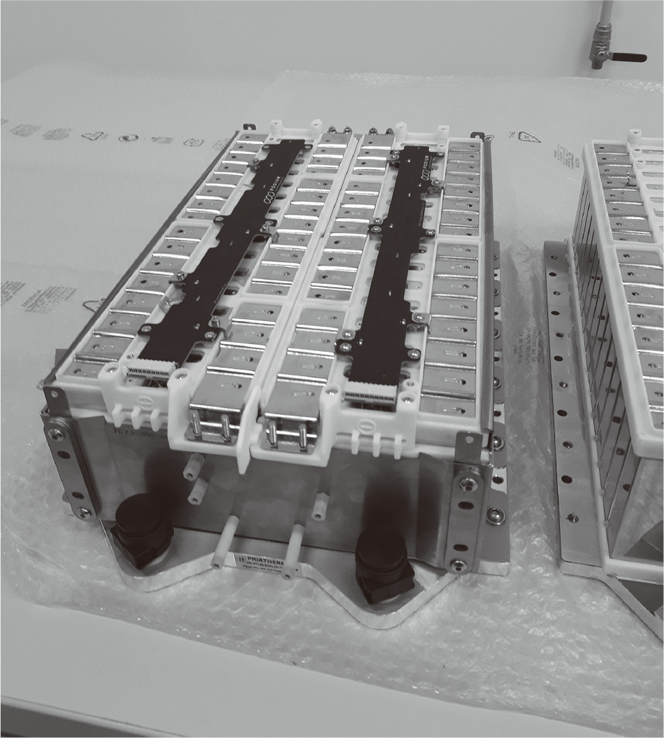 The battery module is made up of thirty-two lithium-ion cells connected in eight series/four parallel (8S4P) configuration.
The actual streetcar system uses 20 of these modules connected in series. Figure 6 shows a prototype system ready for testing and Table 2 lists the main characteristics.
Table 2—OBESS Characteristics

Fig. 6—Photograph of Energy Storage System Prototype.
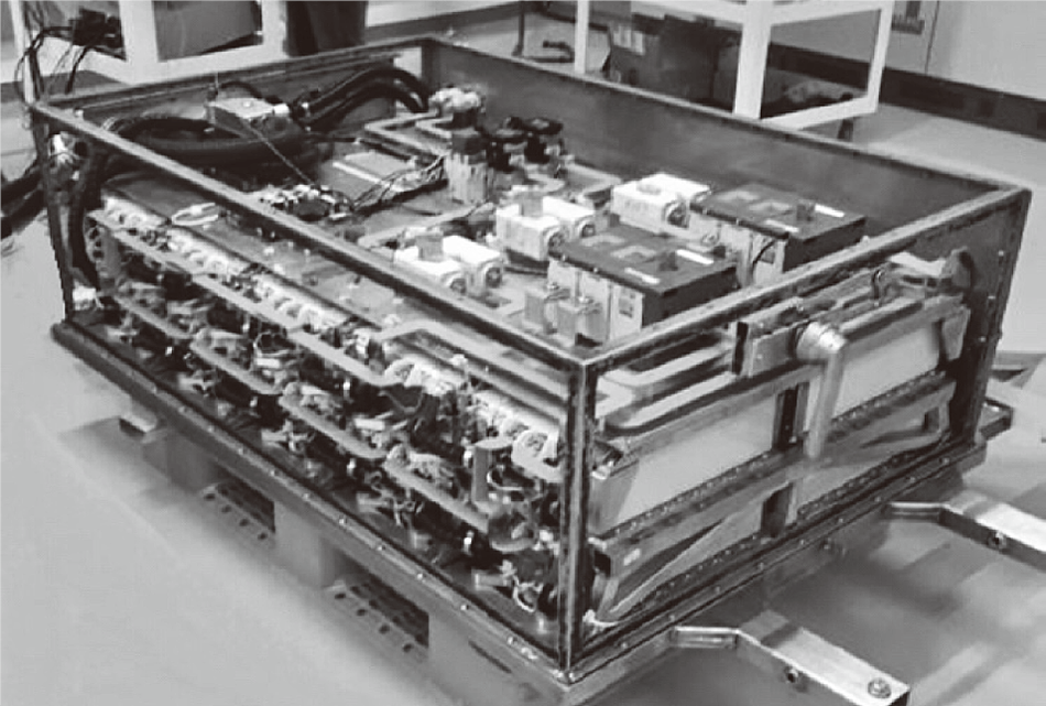 The battery is made up of 20 modules connected in series.
The BMS combines important safety functions with logic and interface functions. Figure 7 shows a block diagram of the BMS that highlights its master-slave architecture.
The main safety functions are:
Other functions include:
Fig. 7—BMS Block Diagram
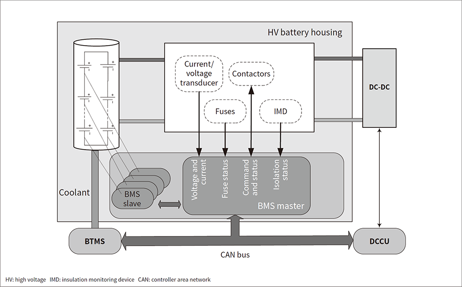 The BMS uses a conventional insulated master–slave architecture. A CAN bus is used to connect the BTMS, BMS, and DCCU.
The storage battery system was designed such that, in its commercialized form, it would be compliant with the IEC 62928 “Rolling stock – Onboard lithium-ion traction batteries” and IEC 62864-1 “Rolling stock – Power supply with onboard energy storage system – Part 1: Series hybrid system” international standards.
Compliance with these standards is required in Europe for vehicle homologation (regulatory approval to allow for commercial use).
The trial route chosen for a practical demonstration of the battery-powered Sirio streetcars* is a 1.3 km long section of the T1 line through central Florence, running from the Santa Maria Novella railway station to Strozzi-Fallaci, with stops at Valfonda and Fortezza.
The Sirio prototype with OBESS is heavier than a standard streetcar and has slower acceleration (0.8 m/s2 compared to 1.10 m/s2). However, this difference does not cause any problems in practice.
Figure 8 shows a simulation of the two vehicles along the trial route and demonstrates how the two streetcars have similar speed profiles with approximately the same average speed. The conclusion is that fitting a streetcar with the OBESS does not significantly affect its speed in commercial operation, especially when used in areas like the historic city center where speed restrictions apply.
Fig. 8—Comparison of Speed and Discharge Curves on Demonstration Route
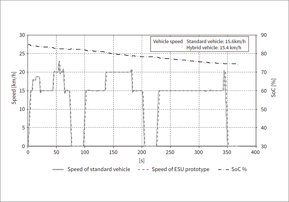 The two curves show that the different weights and accelerations of the standard and OBESS-equipped vehicles did not significantly affect speed during commercial operation on the route under test.
Growth in the market for streetcars means that vehicles able to travel through areas without overhead catenary infrastructure are also needed to cater for locations such as historic city centers.
Hitachi Rail S.p.A has developed a flexible OBESS capable of being installed on the roof of existing vehicles, allowing the use of such vehicles on catenary-free lines. The first prototype demonstrator of this system has been produced and is now undergoing validation testing at its Naples test bench. Trials on the Sirio streetcar are planned for the city of Florence during the summer of 2020 to demonstrate the safety and performance of the system. The next step will be to move on from the prototype to commercial production, including homologation in accordance with applicable standards to enable commercial applications.
