Railway systems have a smaller impact on the environment than other means of transportation such as automobiles and airplanes. Thanks to advances in induction motors and power devices (a core technology for power electronics), the performance, efficiency, miniaturization, and reliability of rolling stock traction systems have been enhanced. Hitachi, Ltd. has developed energy-efficient traction drive systems and traction systems through the use of compact inverters that use low-loss power devices based on a new material, SiC, as well as induction motors designed for lower harmonic losses, the development of PWM control techniques, and improved running profiles. Hitachi is taking advantage of these developments to meet the demand from railway operators for energy efficiency, while continuing to promote global expansion, and to supply railway systems that excel in safety, comfort, and environmental performance.
Process Designing Department, Mito Rail Systems Product Division, Railway Systems Business Unit, Hitachi, Ltd. He is currently engaged in the coordination of the development of power converters for railway vehicles. Dr. Ishikawa is a senior member of the Institute of Electrical Engineers of Japan (IEEJ).
Rolling Stock Electrical Systems Design Department, Mito Rail Systems Product Division, Railway Systems Business Unit, Hitachi, Ltd. He is currently engaged in the coordination of the development and design of power converters for railway vehicles. Mr. Terasawa is a member of the IEEJ.

Process Designing Department, Mito Rail Systems Product Division, Railway Systems Business Unit, Hitachi, Ltd. He is currently engaged in the development of the control systems of power converters for railway vehicles. Mr. Sakai is a member of the IEEJ.
Motor Systems Research Department, Center for Technology Innovation – Controls, Research & Development Group, Hitachi, Ltd. He is currently engaged in the research and development of main electric motors for railway vehicles. Mr. Sugimoto is a member of the IEEJ.
Transportation Systems Research Department, Center for Technology Innovation – Mechanical Engineering, Research & Development Group, Hitachi, Ltd. He is currently engaged in the research of safe and energy-efficient railway systems. Mr. Nishino is a member of the Information Processing Society of Japan (IPSJ).
RISING international awareness of the environment in recent years has increased demand for improvements in energy efficiency, including reducing carbon dioxide (CO2) emissions to prevent global warming and using electric vehicles to minimize atmospheric pollution caused by the exhaust emissions of internal combustion engines. The role of railways, which are significantly more efficient than other forms of transportation such as automobiles and airplanes, is becoming more and more important in achieving these goals(1).
The performance, efficiency, miniaturization, and reliability of rolling stock traction systems have been enhanced by advances in power devices (a core technology for power electronics) and by the use of higher-efficiency induction motors. The use of low-loss power devices is important for making inverters and other traction systems smaller, and this has led to greater use of low-loss power devices that use a new material, silicon carbide (SiC), instead of power devices based on silicon (Si).
Expanding the area outputting regeneration torque in induction motors, designing motors that reduce harmonic losses, and using pulse width modulation (PWM) also play important roles in making traction systems more efficient. Improvements in running profiles are also needed.
This article reports on miniaturization and energy-efficient technologies that address these challenges.
Rolling stock traction systems have been made smaller by advances in power devices, high-density mounting, better cooling performance, and smaller peripheral components. Gate turn-off (GTO) inverters using Si-based 4.5-kV GTO thyristors first appeared in power devices in the mid-1980s, and with the subsequent development of high-voltage insulated-gate bipolar transistors (IGBTs) exceeding 2 kV, Hitachi led the world by commercializing the first inverter using IGBTs for the Hibiya Line of what is today Tokyo Metro Co., Ltd.)(2).
High-voltage IGBT modules are now commercially available in 3.3-kV, 4.5-kV, and 6.5-kV models(3). Advances have also been made in recent years in the development of low-loss power devices that use a new material, SiC. SiC has a higher breakdown electric field strength than Si, so diodes can be reduced to only one tenth the thickness of Si diodes. As a result, in theory, the resistance of diodes during conduction can be made more than two orders of magnitude smaller. This helps make power devices smaller and has the potential to enable smaller inverters with simpler cooling systems.
TABLE 1. Measures for Reducing Inverter Volume
The inverter is made smaller by reducing the size of the SiC modules and cooling system, and by reducing the number of internal components.
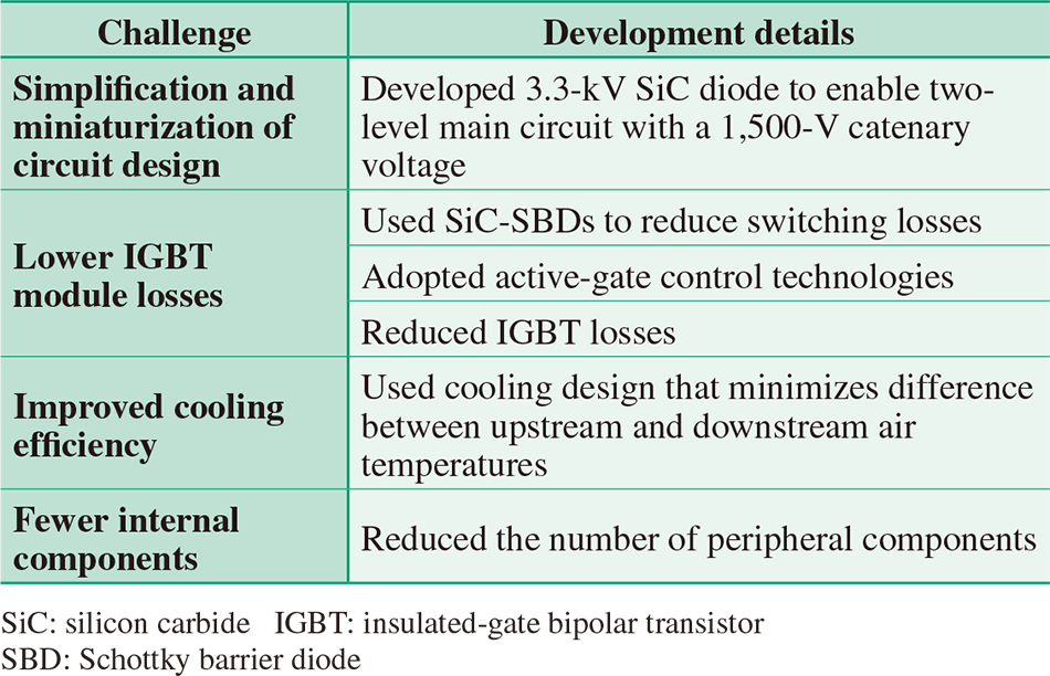
Hitachi led the world in developing a SiC Schottky barrier diode (SBD) for railway applications(4)–(6). Roughly 90% of the electrified sections of track in Japan operate with a catenary voltage of 1.5 kV, and this voltage is also common globally. With a catenary voltage of 1.5 kV, a two-level main circuit design can be achieved using 3.3-kV devices, resulting in a simpler configuration of the main circuit because only two devices are required per phase (compared to six for a three-level design).
Table 1 shows ways of reducing the volume of an inverter.
Together with the adoption of SiC-SBDs and the use of active-gate control technologies to reduce switching losses, improvements in IGBT performance have also reduced inverter losses by 35% (see Fig. 1)(7), (8).
By reducing their losses, the SiC modules have been made smaller. Fig. 2 shows a comparison between a SiC module and a conventional 3.3-kV/1,200-A IGBT module. The mounting footprint was reduced to about two-thirds, with the same output density.
Hitachi has also developed a cooling method that improves the cooling efficiency of power devices, and reduced the number of internal components to make its inverters 40% smaller and lighter (see Fig. 3).
Fig. 1—Comparison of Total Losses for IGBT and SiC Modules. The adoption of SiC diodes, improvements in IGBT performance, and the adoption of active-gate control technologies reduces losses by 35%.
Fig. 2—Exterior of IGBT and SiC Modules. The mounting footprint is reduced to about two-thirds, with the same output density.
Fig. 3—Exterior of Conventional IGBT Inverter and New SiC Inverter.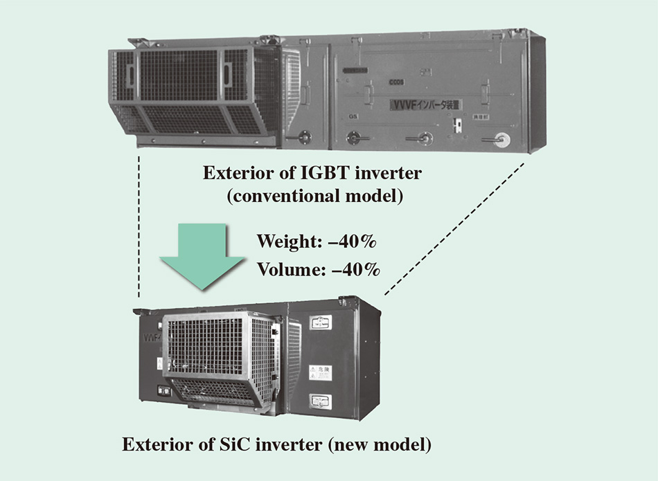 The new inverter is 40% smaller in terms of both weight and volume.
To provide high efficiency drive systems, Hitachi has reduced the energy consumption rate for railway vehicles by expanding the area outputting regeneration torque to minimize use of the pneumatic brakes. Hitachi has also focused on the high harmonic losses of induction motors to reduce power consumption by optimizing the induction motor design and PWM control techniques (see Fig. 4).
Fig. 4—Power Consumption Reduction Strategies (Energy Consumption Rate for Railway Vehicles).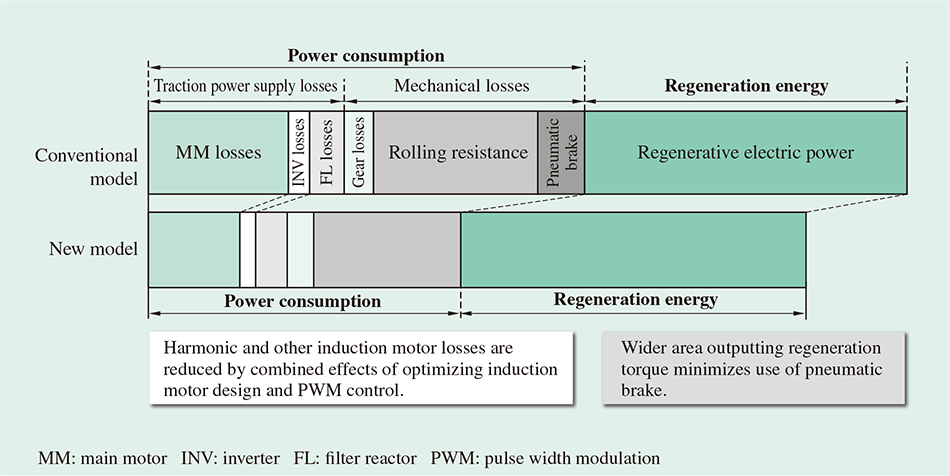 A high efficiency drive system has been achieved by using an induction motor with reduced harmonic losses, PWM control techniques, and a wider area outputting regeneration torque.
Induction motor losses are typically classified as primary copper loss, iron loss, mechanical losses, and stray load losses including harmonic losses. Primary copper loss and iron loss occur as the results of the fundamental (sine wave) component of the waveform. Mechanical loss occurs due to mechanical factors when the induction motor rotates. Harmonic losses include both losses due to the structure of the induction motor, and losses due to distortion of the PWM voltage waveform when driving the inverter.
Although past induction motors have adopted open designs to bring in cooling air from the outside, the use of a fully-enclosed design saves maintenance because it prevents dust from getting into the motor. Primary copper loss has also been reduced by optimizing the stator and rotor designs.
Hitachi has also investigated ways of reducing harmonic losses by using two-dimensional electromagnetic field analysis to optimize the stator teeth magnetic flux density, air gap, and rotor slit height, succeeding in reducing harmonic losses by about 50% compared to past fully-enclosed induction motors(9) (see Fig. 5).
The next step was to reduce harmonic losses by optimizing PWM. Fig. 6 (a) and (b) show the relationships between output voltage and the inverter output fundamental wave frequency and PWM carrier frequency used for PWM control. The motor switches between three different newly developed PWM control techniques depending on the speed.
The harmonic losses of the induction motor have been reduced in the low and medium speed ranges where past practice was to use a combination of asynchronous and synchronous PWM by expanding the control range for asynchronous PWM while inhibiting low-order harmonics through optimization of the carrier frequency and performing PWM control based on the line voltage control type. Current harmonics have been reduced by using low-distortion synchronous PWM control to inhibit the low-order harmonics (fifth and seventh) in the upper end of the medium speed range. In the high-speed range, meanwhile, switching from the conventional synchronous single-pulse traction system to the synchronous triple-pulse traction system with reduced low-order harmonics reduces the harmonic losses of the induction motor while maintaining the same voltage utilization as the synchronous single-pulse traction system.
In motor trials, induction motor losses were reduced by 3.6% when using asynchronous PWM with line-to-line voltage modulation, 8.4% when using low-distortion synchronous PWM in the medium speed range, and 11.1% when using synchronous triple-pulse traction, which is optimal for the high-speed range(10) (see Fig. 7).
Fig. 5—Comparison of Losses for Conventional and New Fully-enclosed Induction Motors.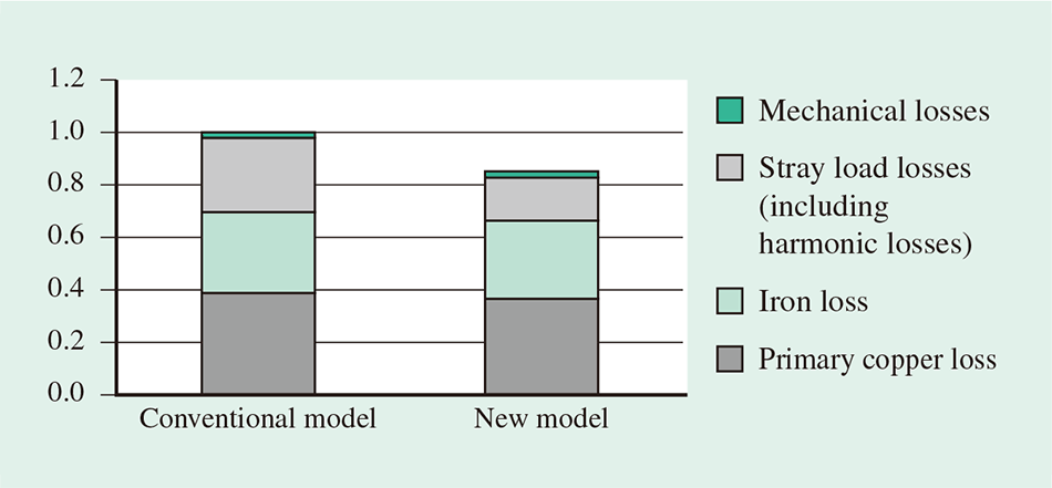 The harmonic losses in the new motor are roughly 50% less than the conventional motor.
Fig. 6—Conventional PWM Control and Proposed Energy-efficient PWM Control. The new inverter reduces harmonic losses by switching between three different PWM control techniques depending on the speed.
Fig. 7—Reduction in Induction Motor Losses Observed in Motor Trials.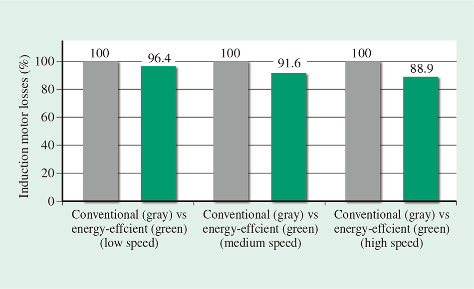 The new PWM control technique reduced harmonic losses at low, medium, and high speeds.
Fig. 8—Verification of Energy Efficiency on Suburban and Commuter Services. The energy consumption rate for a railway vehicle was approximately 40% lower than the conventional system.
The energy consumption rate for a railway vehicle achieved by using SiC modules, induction motors with lower harmonic losses, and PWM control, and by expanding the area outputting regeneration torque, was 37.1% lower relative to conventional systems when tested on existing rolling stock operating on suburban and commuter lines(11) (see Fig. 8).
Fig. 9—Energy-efficient Running Profiles.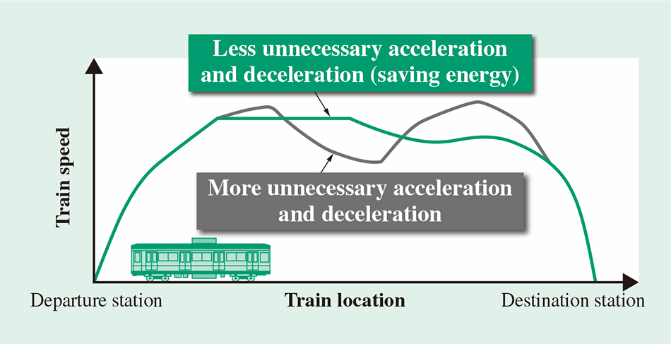 The operation of the train between stations (time spent powering, cruising, coasting, and braking) is determined in a way that reduces energy consumption while still arriving on time.
Fig. 10—Algorithm Developed by Hitachi to Search for Energy-efficient Running Profiles.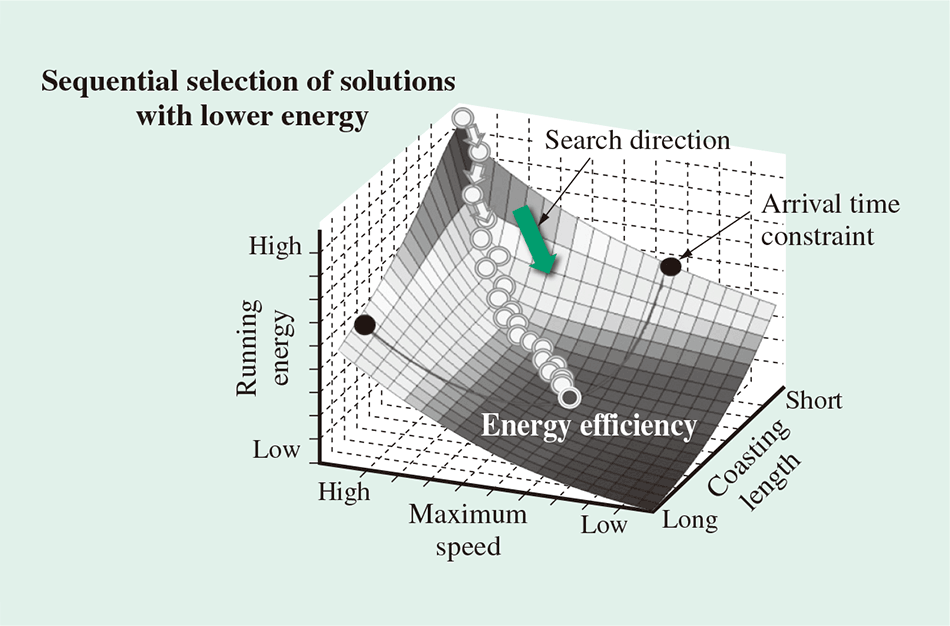 The algorithm obtains a running profile that uses less energy while still arriving on time by progressively decreasing the maximum speed and lengthening the time spent coasting.
The energy consumed to achieve the arrival time specified in a traffic plan can vary depending on the running profile of the train between stations, meaning the amount of time spent powering, cruising, coasting, and braking (see Fig. 9). Hitachi developed an algorithm for obtaining running profiles with low energy consumption so as to achieve energy-efficient operation control(12), (13).
In sections of track where the typical sequence involves powering, cruising, coasting, and then braking, energy consumption is reduced by lengthening the travel time (reducing the maximum speed and spending more time coasting). The developed algorithm takes advantage of this, starting with a top-speed running profile for the section of track and then progressively reducing the maximum speed and lengthening the coasting time by small increments to obtain a running profile that uses less energy but still arrives on time (see Fig. 10). The search process of the developed algorithm also includes a way to update a running profile so that gravitational energy can be used to accelerate the train (when traveling down a gradient). This feature means that using the running profiles obtained by the developed algorithm enables energy-efficient operation control according to the topography of each railway line.
Hitachi has developed compact energy-efficient traction drive systems by adopting individual advanced technologies, including SiC power devices and highly efficient induction motors, and combining these with new techniques that have been enhanced through the use of analytical techniques that it developed leveraging precise, sophisticated simulations.
Hitachi is meeting the demand from railway operators for energy efficiency, while continuing to promote global expansion, and to supply railway systems that excel in safety, comfort, and environmental performance.
