Already becoming a major source of power around the world, wind power generation is looking ever more promising in Japan in terms of supply stability, environmental suitability, and safety. To grow further, providers will need to ensure reliability that meets the needs of installation environments and to offer highly cost-effective wind turbines. This is particularly necessary in coastal waters around Japan, where there is a more demanding environment compared with pioneering wind power areas such as Europe. To address the challenges of the environment, Hitachi has developed 5-MW turbine models for offshore use. These models are intended for use in areas of different wind speeds, high wind speeds and low wind speeds. Hitachi has completed demonstration testing of the high-wind-speed model, and has started demonstration testing of the low-wind-speed model. It is also working on technology for floating offshore wind turbines. This article reports on the development and demonstration of these technologies with a focus on turbine control, which will become important for increasing the reliability and cost-effectiveness of these turbines.
Wind Turbine Generator System Department, Natural Energy Generation Systems Production Division, Power Business Unit, Hitachi, Ltd. Current work and research: Business development of wind turbines. Society memberships: Japan Wind Energy Association (JWEA).

Wind Turbine Generator System Department, Natural Energy Generation Systems Production Division, Power Business Unit, Hitachi, Ltd. Current work and research: Business development of wind turbines. Society memberships: The Institute of Electrical Engineers of Japan (IEEJ).

Wind Turbine Generator System Department, Natural Energy Generation Systems Production Division, Power Business Unit, Hitachi, Ltd. Current work and research: Research and development of wind turbine control. Society memberships: IEEJ and The Japan Society of Mechanical Engineers (JSME).
Natural Energy Generation Systems Production Division, Power Business Unit, Hitachi, Ltd. Current work and research: Wind turbine development project. Society memberships: IEEJ.
Renewable energy is becoming a major source of energy, surpassing the worldwide facility capacity of coal-fired power generation in 2015(1). In a discussion of energy mix, Japan’s Ministry of Economy, Trade and Industry has expressed a goal of helping renewable energy grow from the 12.8% market share it had in 2014, to a 22% to 24% share by 2030. Wind power generation accounts for 1.7% of the market share in Japan(2). One of the challenges facing wind power generation in Japan is to develop wind turbines that are suited to Japan’s demanding environment. Offshore models are needed that can withstand typhoons, earthquakes, and lightning strikes(3).
To meet this public demand, Hitachi has developed 5-MW wind turbines with enhanced reliability and intended for offshore use. It has also started demonstration testing of a floating offshore wind turbine that can be installed in the open ocean to enable more stable and higher-capacity power generation.
This article discusses the specifications, characteristics, and development of these wind turbines. It looks at the demonstrations being done with demonstration models and the development being done on floating offshore wind turbines, focusing mainly on control technology.
Table 1 — HTW 5.2-127 and HTW 5.2-136 Basic Specifications
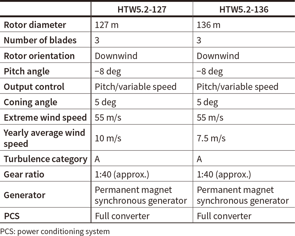 The HTW 5.2-127 was developed for areas of high wind speeds, and the HTW 5.2-136 for areas of low wind speeds.
An overview of the specifications (see Table 1) and concepts(4), (5) of Hitachi’s 5-MW wind turbines is given below.
The following three main measures are designed to lower costs:
The following three main measures are designed to improve reliability:
Figure 1 — HTW 5.2-136 Power Curve
 The graph shows the correlation between wind speed (at the turbine hub height of the wind mast) and power.
Hitachi has conducted several elemental investigations so far, including load tests and lightning tests for the blades, and back-to-back tests and model tests for the drive train. Factory testing has also been done to investigate control and vibration characteristics(5), (7). Subsequently, demonstration testing was performed on a land-based demonstration model of the HTW 5.2-127 for about one year, verifying characteristics such as power generation performance and durability(8), (9).
In September 2016, Hitachi lengthened the blades of this demonstration model to create a demonstration model for the HTW 5.2-136. It replaced the gearbox with a Japanese-made model at the same time. After test operation, it went into commercial operation in November 2016, and Hitachi is now collecting various types of data from it. The HTW 5.2-136 demonstration model has been confirmed to nearly satisfy the power generation performance initially planned (see Figure 1), and development is approaching its final phase.
Table 2 — FRT Test Conditions
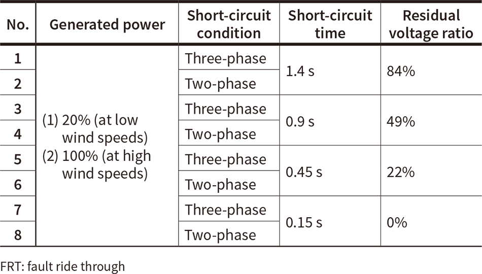 The conditions were set in accordance with grid connection regulations.
As wind power generation has become more widespread and gained a greater share of total generated power, wind power providers are (like conventional power providers) being called on to preserve the grid voltage by maintaining power generation during short-duration grid faults (a capability known as fault ride through, or FRT)(10). Hitachi therefore included a control system to support FRT in the HTW 5.2-127 and verified it using the demonstration model. Hitachi’s evaluation of the system’s electrical characteristics has been reported previously(9), (11). This article reports on the control features and a mechanical evaluation of the system.
The low-speed shaft rotor (composed mostly of the blades) has a higher moment of inertia than the generator rotor even after accounting for the gear ratio of the gearbox. When a grid fault or similar problem suddenly reduces generator torque, the rotational speed of the entire drive train increases and it starts vibrating at its natural frequency. If the grid voltage is restored and the generator torque increases to its previous level, the drive train’s natural vibration acts together with the new torque input to generate a large torque if the timing is poor. The equipment could be damaged as a result, so the following two steps were taken to combat this problem:
The ratio of residual grid voltage during a grid fault is given as a function of fault time(10). Hitachi used this function to set the test conditions (see Table 2). The most mechanically demanding result was obtained from test No. 8 (0.15 s short-circuit time, 0% voltage ratio, two-phase short circuit) (see Figures 2 to 5). After the grid voltage was restored (at a time of 0.15 s), the vibrations were reduced by increasing generator torque at times between 0.5 and 1.0 s instead of increasing it right away, successfully reducing the torque of the high- and low-speed shafts to within their tolerance values.
Figure 2 — Generator Torque during FRT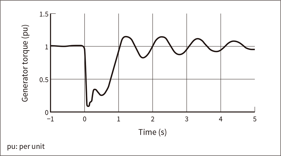 The graph shows the measurement values normalized by rating. A grid fault occurred between the 0 and 0.15 s mark.
Figure 3 — Generator Rotational Speed during FRT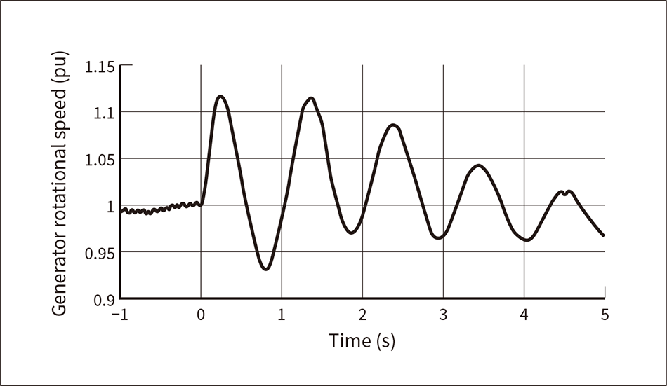 The graph shows the measurement values normalized by rating.
Figure 4 — High-speed Shaft Torque during FRT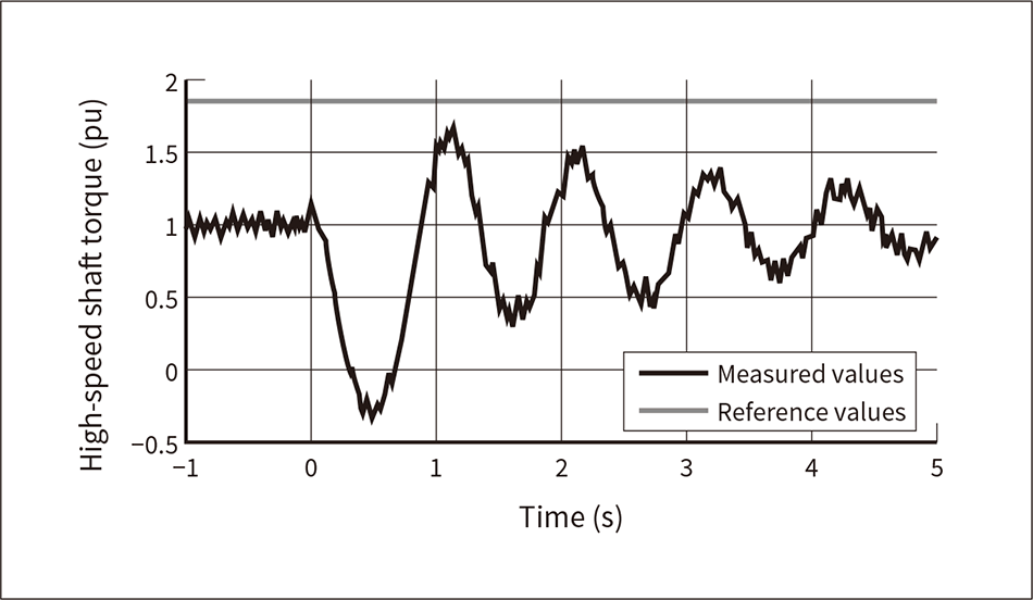 The values in the graph have been calculated from the generator’s torque and rotational speed, taking transient phenomena into account. The values are normalized by rating.
Figure 5 — Low-speed Shaft Torque during FRT
 The values in the graph have been calculated from the strain measured in the low-speed shaft, and are normalized by rating.
Figure 6 — Wind Speed and Wind Direction/Yaw Error over Time during Typhoon Approach
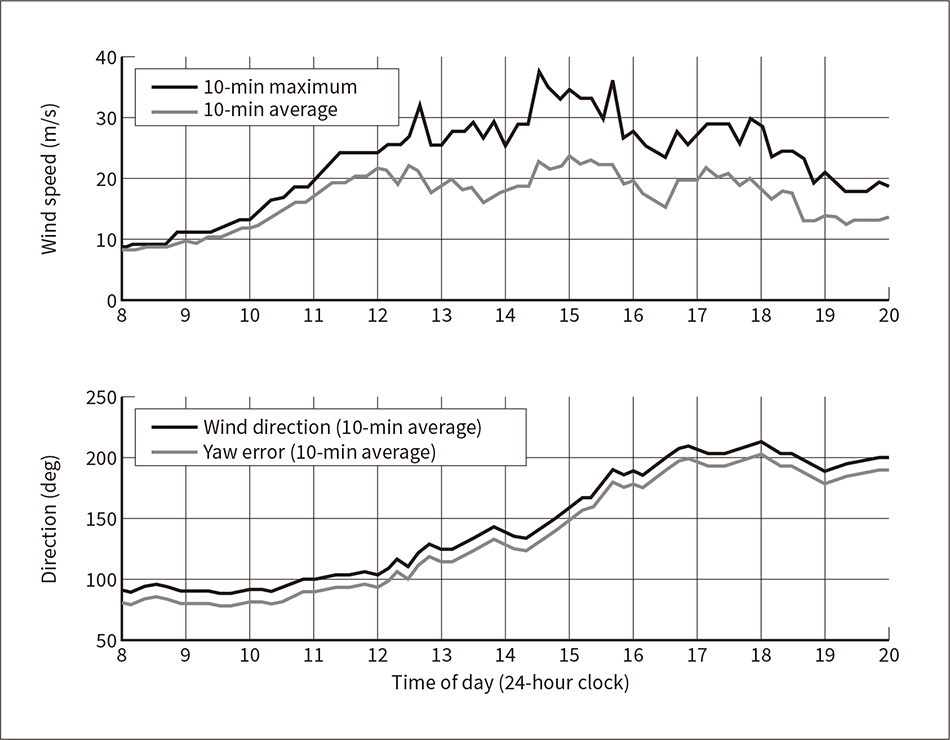 The graphs show statistical values for 10-min intervals, observed from a 90-m wind mast installed about 300 m west-southwest of the turbine. Yaw error is the wind direction minus the nacelle direction angle.
Wind turbine strength design verification requires the use of actual measurements to verify the suitability of loads under the various conditions that the wind turbines are being designed to withstand. The results for the loads during power generation that greatly affect fatigue have previously been reported(8), (9). This article reports on the loads during storm standby that are often critical for static strength.
The design assumes the following three types of yaw control (control causing the rotor plane to follow the wind direction) during storm standby. This article reports the actual measurement results for type (3).
On August 22, 2016, Typhoon Mindulle made a near approach to the demonstration model installation site. An instantaneous maximum wind speed of 37.7 m/s was observed at the wind mast (90 m high) installed near the wind turbine, and the wind direction changed from 100 to 200 deg over a period of about 6 h (see Figure 6). The turbine experienced an abnormal shutdown at this time, and no yaw control was performed. It was therefore subject to near-crosswinds (90-deg yaw error) until about 12 PM, and then the wind blew from the direction opposite the normal direction (180-deg yaw error) starting at 4 PM (see Figure 6).
The blade root bending moment (see Figure 7) was nearly constant between 8 and 9 AM since the wind speed was low and the rotor did not rotate freely. When the rotor started rotating freely, the bending moment changed, and the maximum value of 0.277 times the design value was observed around 3 PM when the wind speed was high.
The tower base bending moment (see Figure 8) was higher in the wind turbine’s lateral direction than in the forward/backward direction. The average values of the lateral bending moment rose as the wind speed of the crosswind rose until noon. Subsequently, the wind speed increased and the variation in bending moment increased. The maximum value of 0.207 times the design value was observed at around 3 PM.
Hitachi will continue to study these wind turbines to determine whether extreme loads are a problem at the design wind speeds. It also plans to gather and evaluate storm standby data under active and passive yaw control.
Figure 7 — Blade Root Bending Moment over Time during Typhoon Approach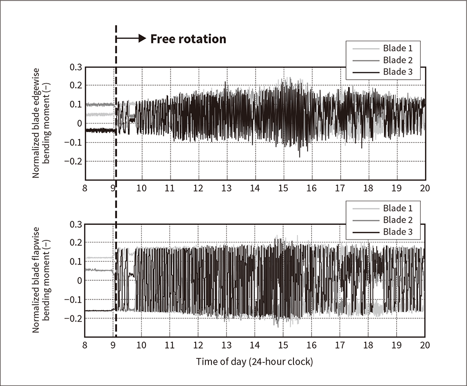 The graphs show the edgewise (top) and flapwise (bottom) bending moments calculated from the measured strain. The values have been normalized by design extreme load. The measurement sampling rate was 50 Hz.
Figure 8 — Tower Base Bending Moment over Time during Typhoon Approach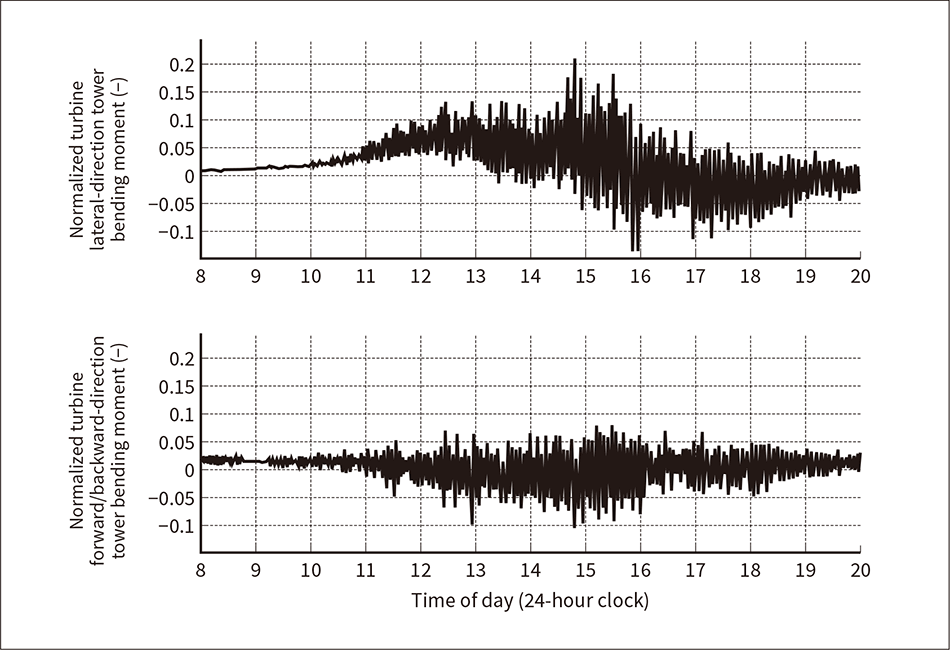 The graphs show the turbine lateral-direction (top) and turbine forward/backward-direction (bottom) bending moments calculated from the strain measured in the tower base and nacelle direction angle. The values have been normalized by design extreme load. The measurement sampling rate was 50 Hz.
This section discusses the development of a floating offshore wind turbine created as part of the Fukushima Floating Offshore Wind Farm Demonstration Project funded by the Ministry of Economy, Trade and Industry(12). The system consists of the 5-MW wind turbine described above installed on a floating offshore structure (see Figure 9).
The floating structure (“floater”) is an advanced spar containing hexagonal plate-shaped structures (upper and lower hulls) at the top and bottom of a cylindrical structure. Advanced spars have upper and lower hulls to reduce the oscillation of the floating structure in wave surges, thereby controlling the increase in floater height compared with the so-called spar type. This characteristic eliminates the need for the difficult work required for the spar type such as erecting the spar offshore. The floater was installed off the coast of Fukushima in July 2016, the grid cable connection was completed, and the system started receiving power in September. Test operation was conducted until March 2017, and Hitachi has been demonstrating power generation since April.
Floating offshore wind turbines are installed on offshore floaters and so are prone to changes forward/backward posture (pitch angle). The blade pitch angle is adjusted to keep the rotor speed at the rated value when generating power, which causes pitching oscillations (a phenomenon known as negative damping).
During the Ministry of the Environment’s Floating Offshore Wind Turbine Demonstration Project (which continued through FY2015), Hitachi developed a control technique called floating platform vibration control (FVC), which reduced negative damping in a 2-MW floating offshore wind turbine(13)–(15). Using an inclination angle sensor mounted in the nacelle, FVC detects the pitch angle and manipulates the blade pitch angle to adjust the thrust force received by the rotor, thereby reducing pitching oscillations. Hitachi plans to use FVC in the Fukushima 5-MW floating turbine to improve performance and verify the feasibility of using FVC with a 5-MW wind turbine and advanced spar floater. In preparation for using the actual facility for test operation and power generation demonstrations, Hitachi has conducted simulations to demonstrate that FVC will be able to reduce negative damping in the Fukushima 5-MW floating turbine (see Figure 10).
The system also has a function for independently adjusting the blade pitch angle. Hitachi plans to use this function to adjust the blade pitch angle independently during a single rotor rotation to match the changing condition of the wind in the rotor plane. The function will enable Hitachi to also develop a control technique that can reduce the bending load generated on the rotor shaft and improve system efficiency.
Figure 9 — Fukushima Hamakaze 5-MW Floating Offshore Wind Turbine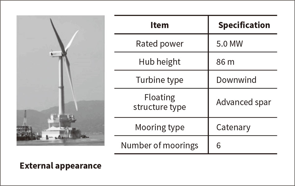 Fukushima Hamakaze was built as part of the Fukushima Floating Offshore Wind Farm Demonstration Project funded by the Ministry of Economy, Trade and Industry.
Figure 10 — 5-MW Floating Offshore Wind Turbine Simulation Results Using an inclination angle sensor mounted in the nacelle, FVC detects the pitching oscillations in forward/backward direction and manipulates the blade pitch angle to adjust the thrust force received from the wind. FVC thereby reduces oscillations in the nacelle’s pitch angle (system’s forward/backward tilt angle), enabling stable power generation.
Focusing on turbine control, this article has presented Hitachi’s development of 5-MW wind turbines, demonstration testing on demonstration models, and its work on a floating offshore wind turbine.
By successfully completing the development of the 5-MW wind turbines and demonstrating them on floaters, Hitachi is looking toward providing highly reliable products to the offshore wind power market—an area in which worldwide growth is expected.
Hitachi would like to express its gratitude to the New Energy and Industrial Technology Development Organization (NEDO) for the assistance received in the development of the 5-MW wind power generators.
Hitachi would also like to its consortium partners for their help in the Fukushima Floating Offshore Wind Farm Demonstration Project.
