As the world seeks to secure a diverse range of energy sources that produce low levels of greenhouse gas emissions, nuclear power generation, which can provide a stable supply of large amounts of power, is one effective option. Moreover, as the global demand for energy increases, utilizing reusable fuel (uranium and plutonium) to generate nuclear power that can supply energy over a long period of time can also be seen as effective for improving energy security. Despite this, many domestic nuclear power plants have halted operations, and so an early resumption of operations is desirable. For this reason, Hitachi is strengthening it efforts toward a resumption of operations by working to provide a nuclear power generation system that complies with the new regulatory requirements, and that will achieve the highest level of safety in the world. Hitachi is also working to apply this nuclear power generation system to plants outside Japan, and will continue to promote the provision of energy with excellent ecological compatibility and sustainability around the world.
Public Affairs and Government Relations Department, Hitachi-GE Nuclear Energy, Ltd. Current work and research: Public relations and related activities in the field of nuclear power. Society memberships: Atomic Energy Society of Japan (AESJ).
Plant and Systems Engineering Section, Nuclear Plant Engineering Department, Hitachi-GE Nuclear Energy, Ltd. Current work and research: Section manager, and system design engineering related to nuclear reactors.
The sources of electrical energy, which is a foundation of people's lives and of industry, have been growing increasingly diverse in recent years. In addition to developments in hydroelectric, thermal, and nuclear power, renewable energies such as solar and wind power have also been introduced.
As the world seeks to secure energy sources that produce low levels of greenhouse gas emissions, nuclear power can be seen as an effective option because it offers excellent ecological compatibility and sustainability as an energy source, and it can provide a stable supply of large amounts energy.
Based on these circumstances, in order to contribute to the resumption of nuclear power plant operations in Japan, Hitachi has been promoting the development of safety improvement technology that improves the margin of safety in compliance with new regulatory requirements. As a result, Hitachi has developed countermeasures that can fully clear the target values for safety objectives debated in Japan(1), as well as the safety objectives of the International Atomic Energy Agency (IAEA)(2), for metrics such as frequency of core damage, frequency of containment failure, etc. And, in response to the increasing demand for energy around the world, Hitachi has adopted a policy of providing advanced boiling water reactors (ABWRs), which have excellent safety characteristics and a long track record.
This article describes these efforts by Hitachi, the characteristics of nuclear power generation systems, and the state of the effort to resume nuclear power plant operations in Japan.
In its positioning of nuclear power generation in Japan, the Strategic Energy Plan adopted by the Japanese Cabinet in April 2014 stated, “With its overwhelmingly high energy output with respect to fuel input amount, and its status as a low-carbon semi-domestic energy source for which production can be maintained for several years with only the fuel retained in Japan, its extremely stable supply and efficiency, low operating cost with minimal fluctuations, and lack of greenhouse gas emissions during operation, nuclear power generation is positioned as an important base load source that can contribute to the stability of Japan's energy supply and demand structure based on the key assumption of securing safety.”
Looking outside of Japan, and centering on the Asia region beginning with China, where there is pronounced economic growth, there are plans to install large amounts of nuclear power generation capacity. Japan, which experienced the Fukushima Daiichi Nuclear Power Station accident, will seek to contribute to international society by providing safety technology that reflects the lessons it learned from this accident.
As nuclear power generation expands centered in the Asia region, this will have a long-term effect on the supply and demand of uranium resources. Considering the uranium resource reserves, which are said to be enough for several decades, it is likely to become increasingly necessary to promote the effective utilization of non-fissile uranium-238, which amounts to approximately 99.3% of naturally occurring uranium. At present, the mainstream power generation technique is to enrich the fissile uranium-235 content, which makes up approximately 0.7% of the total uranium resources, into concentrations between 3% and 5% for use in light-water reactors. On the other hand, spent fuel contains plutonium-239 as a useful resource, and projects are being carried out with the goal of generating power by reprocessing spent fuel to extract the plutonium-239 and mixing it with uranium to create a mixed oxide (MOX) fuel that can be burned again in light-water reactors. Although there are already a small number of fuel assemblies that have loaded and successfully burned this fuel, in the future Electric Power Development Co., Ltd. plans to utilize the fuel at Ohma Nuclear Power Plant as full MOX, and is currently preparing for being reviewed on the new regulatory requirements. Also, by completing the fast reactor cycle, it will be possible to improve the utilization of uranium resources even further, thereby enabling the supply of enough energy for several thousand years. Although the spent fuel of a fast reactor includes substances with half-lives in excess of several tens of thousands of years, it is possible to use in-pile nuclear fission to destroy this material to provide still more long-term resource stability and reduced environmental load at the same time.
At present, nuclear power generation with a higher level of safety is being earnestly examined in Japan, and the gradual resumption of operations is about to begin. On the other hand, capital investment aimed at improving safety affects the economic efficiency of nuclear power generation, and so more effective countermeasures are required. The Fukushima Daiichi Nuclear Power Station was hit by a natural phenomenon that exceeded its design, resulting in a severe accident. When it comes to phenomena that exceed the design, flexible thinking that goes beyond simply strengthening the design, such as the use of backup facilities as alternatives, or receiving aggressive support from outside reactor facilities, will become increasingly important. Hitachi is proposing and implementing rational countermeasures, including those for operations, based on its experiences with the new domestic regulations and with projects pursued in the UK. Its major efforts are described below.
The Great East Japan Earthquake of March 2011 and the accident at the Fukushima Daiichi Nuclear Power Station run by Tokyo Electric Power Company Holdings, Incorporated did a great deal of damage in Japan. Hitachi responded earnestly to this accident by providing extensive support for the recovery and reconstruction of the disaster-stricken region and the Fukushima Daiichi Nuclear Power Station, while also working to restore trust in nuclear power(3), (4).
Hitachi's basic policies regarding safety measures based on the lessons learned from the Fukushima Daiichi Nuclear Power Station accident are described below. There are also plans to incorporate these basic policies into plants overseas, in addition to domestic plants. Specifically, Hitachi is designing an ABWR with increased safety in order to construct nuclear power plants in the UK in coordination with British regulators.
Table 1 — Securing Plant Safety through Defense in Depth
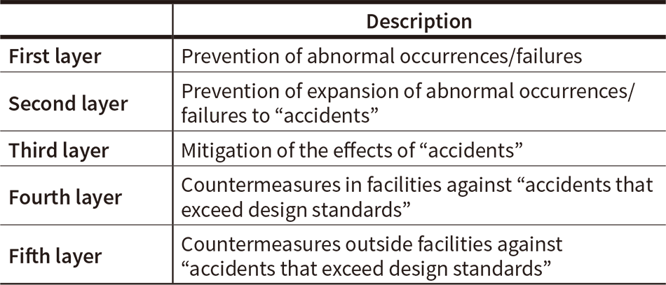 In addition to the three layers (prevention of abnormal occurrences, prevention of the expansion of abnormal occurrences, and mitigation of the effects of accidents) used to secure the safety of nuclear power facilities, five additional layers are used to respond to accidents, including severe ones.
The following three items are important basic policies for safety measures that were designed based on the experience and lessons of the Fukushima Daiichi Nuclear Power Station accident in order to prevent widespread damage at a site from a large-scale earthquake or tsunami.
The first policy is to protect important safety equipment from the designed reference load by an external event. For instance, this includes seawalls, watertight doors for buildings, and placing equipment used to deal with full alternating current (AC) blackouts in decentralized locations.
The second policy is to use portable equipment to prepare flexible responses to situations when the protection of this safety equipment is breached (as a countermeasure against external events that exceed design conditions). Furthermore, improvements in the resistance of nuclear reactor containment vessels (“containment vessels” hereinafter) with respect to leaks of radioactive material are also important.
The third policy is to prepare a concise strategy that considers effectiveness in case an entire site is severely damaged by a large-scale external event, and to prepare countermeasures for implementing coordinated on-site and off-site responses.
This philosophy uses “defense in depth” to ensure a plant's safety as well. The application of defense in depth to secure the safety of nuclear power facilities requires five layers of safeguards to protect the public, as broadly outlined in Table 1.
These basic policies for safety measures, which stem from the lessons of the Fukushima Daiichi Nuclear Power Station accident, are designed to strengthen each layer of the defense in depth, including boundaries between the layers such as the effective utilization of off-site resources.
This section describes the state of implementing safety equipment considering the basic policies for safety measures and the new regulatory requirements.
The following overview describes four broad categories of safety equipment that can be strengthened as further safety measures. Note that it is not necessary to install all of the listed equipment, but each plant will need to select the appropriate equipment based on that specific plant's yield strength.
Equipment for handling design basis accidents can be strengthened according to these concrete recommendations based on an evaluation of the effects of internal fires, internal overflows, external events (volcanos, tornados, external fires), etc. There are two major ways in which equipment can be strengthened for handling design basis accidents.
Implement equipment countermeasures against internal fires to maintain safety.
Implement equipment countermeasures against internal overflows to maintain safety.
Equipment is permanently installed so that it can function quickly to prevent severe core damage, to prevent damage to the containment vessel, to inhibit the release of radioactive material, and to mitigate the diffusion of radioactive material, etc. Examples of the main equipment installed for handling major accidents are described below.
Low-pressure alternative water injection equipment is installed as versatile water injection system to use as a countermeasure against design basis accidents, so that core damage can be prevented by injecting water into the nuclear reactor even if an accident occurs that exceeds the design standards.
Equipment is installed to vent the containment vessel to the outside in order to release heat while protecting against over-pressurization. Since this emits gas from the containment vessel to outside the system, installing this filter vent equipment in the path of the emission makes it possible to capture the radioactive aerosols included in the gas, thereby reducing radioactive emissions.
Equipment is installed inside the containment vessel to remove heat, and to prevent damage by cooling the containment vessel. It is also possible to use a portable water injection pump since there is sufficient time before it is necessary to spray the containment vessel. In this case, the connection ports for the pumps are installed in two locations outside the building for the sake of decentralization, and the burden on the operator is reduced by permanently installing the connections from the external connection ports to the containment vessel spraying equipment.
PARs are installed inside the nuclear reactor building to keep the hydrogen concentration below the flammability limit even if core damage causes the hydrogen gas emitted into the containment vessel to leak into the nuclear reactor building. Three-dimensional flow analysis technology is utilized to select suitable locations for installing the PARs.
Water injection equipment is installed to fill the reactor well to remove heat from the containment vessel, and to promote cooling of the top of the containment vessel to prevent damage to gaskets and other non-metallic parts that are easily damaged by heat. It is also possible to use a portable water injection pump since there is sufficient time before it is necessary to inject water into the reactor well. In this case, the connection ports for the pumps are installed in two locations outside the building for the sake of decentralization, and the burden on the operator is reduced by permanently installing the connections from the external connection ports to the reactor well.
Water injection equipment is installed to fill the bottom of the containment vessel to cool the reactor core if it suffers severe damage, causing it to melt and fall to the bottom of the containment vessel. It is also possible to use a portable water injection pump since there is sufficient time before it is necessary to inject water into the bottom of the containment vessel. In this case, the connection ports for the pumps are installed in two locations outside the building for the sake of decentralization, and the burden on the operator is reduced by permanently installing the connections from the external connection ports to the bottom of the containment vessel.
Equipment is installed to supply the fuel pool with water and cool it to prevent damage to the fuel. The equipment provides versatility for cooling the fuel pool as a countermeasure against design basis accidents. It is also possible to use a portable water injection pump since there is sufficient time before it is necessary to cool the fuel pool. In this case, connection ports for the pumps are installed in two locations outside the building for the sake of decentralization, and the burden on the operator, in terms of having to install the equipment when using it, is reduced by permanently installing the connections from the external connection ports to the fuel pool. Furthermore, if a destructive act of terrorism or other incident of a scale that is difficult to predict occurs, spraying equipment is installed to discharge water onto the fuel pool while spraying the fuel, in a dual-function configuration that injects water and sprays at the same time.
High-pressure alternative water injection equipment is installed so that core damage can be prevented by injecting water into the nuclear reactor. As a substitute for a reactor core isolation cooling system (RCIC), this equipment is a countermeasure against design basis accidents, even when the nuclear reactor is in a high-pressure state.
The main steam release safety valve's opening operation has been enhanced by deploying reserve nitrogen gas containers that provide driving force, by strengthening the opening operation caused by the rising pressure of the driving force, or by strengthening the power source installed to power the opening operation for handling events that exceed design standards. Furthermore, development is proceeding on equipment that enables the opening operation of the main steam release safety valve just by using nitrogen gas as the driving force, without requiring a power source.
As with permanent equipment, equipment for dealing with major accidents, etc. (portable equipment) is also installed for use during major accidents in order to prevent severe damage to the core or containment vessel, to suppress the emission of radioactive material, and to mitigate their diffusion, etc. The assumption is that even if portable equipment functions for the necessary length of time after it is transported, installed, and otherwise set up to be used, it will still serve its purpose in the system, such as the prevention of core damage.
Two examples of the main portable equipment installed for handling major accidents are given below.
Alternative component cooling water equipment is installed to use as an alternative to the component cooling water system that is used as a countermeasure against design basis accidents. This can include equipment such as pumps and heat exchangers in a mobile trailer that can be used instead of the component cooling water equipment.
Water conveyance vehicles are deployed as portable equipment to feed water from water sources to containment vessel spraying equipment, reactor well water injection equipment, and fuel pool water injection/spraying equipment for handling major accidents.
Equipment is installed to provide functions that are needed to deal with severe accidents, etc. caused by terrorism, such as the intentional crashing of a large airplane into a nuclear reactor building.
This basically includes nuclear reactor water injection equipment, containment vessel spraying equipment, nuclear reactor pressure reduction equipment, fuel pool water injection and spraying equipment, and the construction of a disaster prevention building that houses equipment such as power equipment and instrumentation.
Details of the main permanent equipment installed for dealing with severe accidents are described below.
Figure 1 — Structure of the Filter Vent System
 The filter vent system includes a Venturi nozzle (scrubber) and metal filter that work in combination to efficiently capture aerosols. The scrubber supplies gas, which flows at high speed through the Venturi nozzle, with a circumference of scrubbing water microdroplets to mix the gas with liquid and to improve the aerosol adsorption effect.
A number of different countermeasures are planned in order to ensure the soundness of the containment vessel even if there is damage to the reactor core due to a severe accident. These countermeasures include injecting water into the containment vessel, cooling the containment vessel, securing the necessary power for these operations, etc. Filter vent systems are used when it is difficult to control the pressure in the containment vessel during these operations, in order to reduce radiation by filtering out the radioactive aerosols included in the gas emitted from the containment vessel when reducing the pressure to control it.
Hitachi is currently working on designing, manufacturing, and installing filter vent systems based on wet filter vent technology for boiling water nuclear power plants in Japan, which is being adopted in nuclear power plants. The structure of a filter vent system is shown in Figure 1.
The filter vent systems are constructed of stainless steel with a vertical cylindrical vessel that provides two filter functions. Comparatively coarse aerosols are captured in a Venturi nozzle (scrubber) that acts as the first stage filter for the gas emitted from the containment vessel. After that, the second stage metal filter works to further filter out the finer aerosols.
The following considerations are based on the lessons learned from the Fukushima Daiichi Nuclear Power Station accident.
An electrically driven remote control valve is used to isolate the containment vessel and the filter vent device, which can be manually operated over the shielding wall. The instruments necessary for operating around the filter vent system are passive instruments that can be monitored.
The inside of the filter vent system is always nitrogen-sealed so that the hydrogen gas will not combust even if it gets into the vent.
Figure 2 — Example Configuration of Reactor Pressure Vessel Decompression Mechanism Using Changeover Valve
 The gas used to drive the SRV is supplied to the driving force supply line that is connected to the changeover valve. The SRV cylinder is pressurized via the changeover valve and the electromagnetic SRV valve, thereby forcing the SRV open without a power source.
If all power sources including direct current (DC) power fail during a severe accident or other problem, then it will not be possible to operate the electromagnetic valve used to operate the steam release safety valve (safety relief valve, or SRV) that directly lowers the pressure of the reactor primary system. This makes it difficult to reduce the pressure of the reactor primary system, which is required in order to inject large amounts of coolant into the reactor core. As an effective direct countermeasure, portable DC power sources or spare power sources are being deployed and installed for use in connecting to this important equipment. As a means of handling this kind of event, a mechanism has been developed that enables the SRV relief valves (“changeover valves”) that reduce pressure in the reactor primary system to operate without power, and is being adopted for use in nuclear power plants.
These changeover valves have two outlets and one shared inlet, and automatically close either the shared inlet or one of the outlets through the effects of inlet pressure. Specifically, the outlet that is normally opened in the changeover valve is connected to the exhaust side of the electromagnetic SRV valve, and the other outlet is exposed to the atmosphere, thereby enabling the supply of gas that drives the SRV through the shared inlet. Given this design, even if all power including DC is lost, and the electromagnetic SRV valve cannot be magnetized, it is still possible to operate the SRV by supplying it with the gas needed to operate it through this changeover valve. An example of a system configuration using this changeover valve as the reactor pressure vessel decompression mechanism is shown in Figure 2. Also, note that this type of changeover valve can be used for other air-operated valves that must be forced open as a failsafe, and is not limited to just SRVs.
RCICs have been used in the past as systems for injecting high-pressure water into a nuclear reactor when a complete loss of AC power occurs (station blackout). The RCIC system does not require AC power to operate the turbine-driven pump with the steam generated by the nuclear reactor.
The high-pressure alternative water injection system uses a turbine water lubricated (TWL) turbine pump and, as a system that uses a turbine-driven pump just like the RCIC, it can be added as a backup to the RCIC (see Figure 3) and is being adopted for use in nuclear power plants. Optimal system configurations are being considered and proposed for use during severe accidents, based on the lessons learned from the Fukushima Daiichi Nuclear Power Station accident.
TWL-type turbine pumps have the following characteristics. They are integrated turbine and pump components that are smaller than traditional RCIC turbine pumps, and can be made more compact because they do not require gland seal devices (condensers, vacuum tanks, vacuum pumps, etc., see Figure 4). Also, since they use a water-lubricated bearing system, they do not require lubricating oil systems, and this increases their flexibility in terms of installation locations.
This pump has the same flow rate and lift as an RCIC pump in high-pressure conditions. The pump discharge flow rate is adjusted by a mechanical adjustment mechanism inside the component, and does not have an electrical control system, so this also helps lower the consumption of electric power during control.
TWL turbine pumps have been adopted for use as RCIC pumps in the Lungmen Nuclear Power Plant, and there are also plans to adopt them as RCIC pumps in ABWRs to be deployed overseas.
Figure 3 — Exterior of the TWL Type Turbine Pump
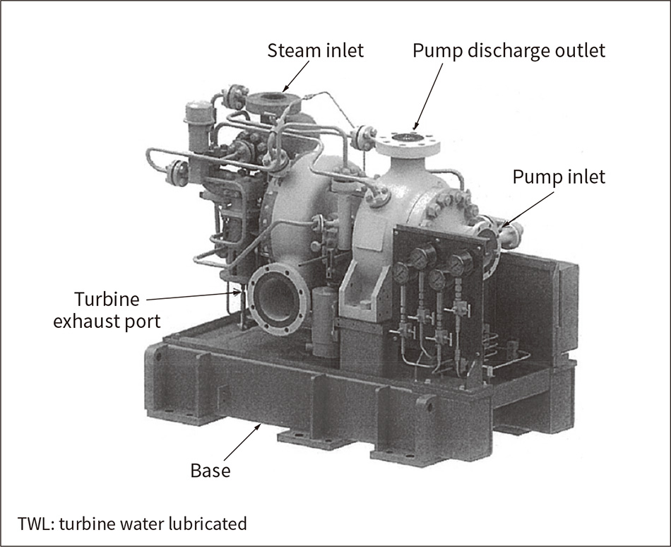 The exterior of the integrated TWL type turbine pump is shown above. The adoption of a water-lubricated bearing method and mechanical seal eliminates the need for a lubricating oil system and a gland seal device.
Figure 4 — Size Comparison of TWL and Conventional RCIC Pump Types
 The TWL turbine pump is more compact than the conventional RCIC pump, and offers more flexibility when it comes to installation locations.
Nuclear power generation plants can be seen as an important source of Japan's power, and a key component of the stable energy mix that is helping strengthen its national energy security. Hitachi will continue to provide nuclear power generation plants that are even safer by applying the lessons learned from the Fukushima Daiichi Nuclear Power Station accident. The technologies described here can also be used to support the safe resumption of operations at existing plants, by contributing to the operation and construction of plants that are even safer and more trusted. Furthermore, these technologies are expected to be applied at nuclear power plants overseas as well, and will continue to contribute to meeting the global increase in demand for energy as facilities are deployed worldwide.
