Autonomous Driving Technology for Connected Cars
Progress is being made on vehicle periphery sensing, the greatest challenge to overcome for autonomous driving. This article describes key examples of such techniques for sensing of vehicle periphery and localization, including improvements in stereo camera performance, ultra-miniaturization of millimeter-wave radar, further development of SurroundEye, and a localization technique that uses lane markings and map matching.
![]()
The industry has been competing to develop advanced driver-assistance systems (ADAS) since the announcement of Subaru Corporation's EyeSight* (ver.2) in 2010, with this competition becoming even more intense in recent years as the focus has shifted to autonomous driving. To coincide with sports events in 2020, the Japanese government is pursuing development in key areas required for automated driving systems, with the aim of developing a next-generation traffic system in collaboration with the Tokyo Metropolitan Government. Hitachi is also proceeding with research and development based on a similar roadmap.
Driving automation level is classified into six levels (levels 0 to 5) based on the role that the system plays in driving the vehicle. Levels 1 and 2 correspond to ADAS functions, with the driver remaining responsible for driving. Responsibility for driving shifts to the system at levels 3 and higher, and it is these levels that correspond to autonomous driving as the term is commonly used.
Autonomous driving requires that the following three processes be executed rapidly and repetitively.
Figure 1 - Vehicle Periphery Sensing and Localization
 Autonomous driving requires not only the recognition of nearby vehicles and white lines, but also the use of map-matching for localization (to formulate a trajectory plan based on the estimated vehicle position).
Obviously, safe autonomous driving cannot be achieved if the area around the vehicle monitored by (1) is too small, regardless of how well the second two processes are performed. This article describes the progress of technology development at Hitachi in relation to vehicle periphery sensing and localization, the greatest challenge to more advanced autonomous driving. Specifically, the article describes improvements in stereo camera performance, ultra-miniaturization of millimeter-wave radar, further development of SurroundEye, and a localization technique that uses lane markings and map matching.
In addition to providing gray-scale images, a stereo camera can also serve as a distance sensor. The parallax (disparity between the left and right camera views) can be measured and the distances calculated using triangulation. The ability to combine recognition of gray-scale patterns and three-dimensional shapes at the level of individual pixels and at high resolution is an advantage over systems with only monocular cameras or with monocular cameras and millimeter-wave radars. Recognizing the importance of a vehicle-mounted stereo camera for front sensing, Hitachi Automotive Systems, Ltd. is putting a lot of effort into its development.
With a view to autonomous driving, recent years have seen particular demand for sensing functions that can identify the “drivable area.” The term “drivable area” used here means not only the vehicle's lane, as identified by conventional lane sensing, but also the physical region within which the vehicle is able to drive based on detecting the edge of the road. Identification of the drivable area is essential for autonomous driving so that the vehicle can plan its own trajectory. Given the performance factors described above, this function can be realized using a single stereo camera unit because the characteristics of the stereo camera are suitable for space recognition at high resolution. For these reasons, Hitachi has developed a technique for using a stereo camera to detect the road edge and drivable area.
Figure 2 shows the road edges and drivable areas detected by the technique. This shows the many different types of road edges that can be identified as well as the drivable area on the road.
Figure 2 - Detection of Road Edges and Drivable Areas
 The red lines indicate the detected road edges. The technique can detect a wide variety of different types of road edges, including guardrails, banks, curbstones, poles, bushes, sidewalls, grass, and the sides of moving and parked vehicles. The green regions indicate the detected drivable area.
One of the challenges was a tendency for shapes on the road boundary to be indistinct, such as the presence of low features such as curbstones or intermittent ones like poles. To overcome this, Hitachi's technique defines the calculation of boundary shapes as an optimal path problem that works by performing a comprehensive search for candidate boundary shapes within the space and identifying the shapes that maximize “boundary likelihood” (1). This “boundary likelihood” is defined in terms of a feature value based on height above road surface and continuity in the depth direction. In this way, reliable estimation even in the presence of features with indistinct boundaries was achieved by adopting a technique based on solving optimal path problems. Road edge detection was also further improved by developing a road surface estimation method that served as a base technique for quickly and accurately determining the height of boundary regions(2).
Figure 3 - Overview of Road Edge Detection
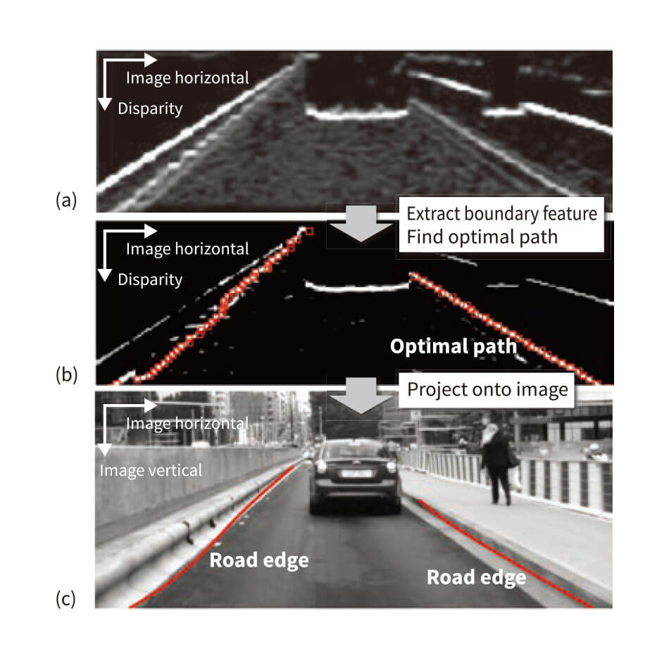 Respectively, images (a), (b), and (c) show the elevation map (map of height above road surface displayed on a bird's eye view), the boundary feature map (map of likelihood of road boundary being present displayed on a bird's eye view), and the results of road edge detection.
Figure 3 shows an overview of road edge detection. Figure 3 (a) shows an elevation map, which indicates the height of boundary regions above road surface, generated from distance measurements made by a stereo camera and road surface estimation. Figure 3 (b) shows a boundary feature map generated by transforming the elevation map that indicates the likelihood of a road boundary being present (defined as the boundary above a certain height that is closest, as seen from the vehicle). Figure 3 (c) shows the results of road edge detection in the form of the optimal paths calculated through the area of the boundary feature map projected onto an image of the road. The drivable area is identified by calculating the region enclosed by the left, right, forward, and backward boundaries.
Two new vehicle control applications were developed using this technique and demonstrated on actual vehicles both inside and outside the company(1), (3).
Because it uses radio waves, millimeter-wave radar is less subject to environmental factors such as rain, fog, darkness, or reflected light. Unfortunately, the way it works makes identification of detected objects difficult. These characteristics mean that, in autonomous driving, it is most commonly used in tandem with camera-based sensors, leading to demand for smaller size and lower cost.
One way to make long-distance millimeter-wave radar smaller and less expensive is to shrink the size of the antenna substrate that accounts for several tenths of the cost. Hitachi sought to make the antenna substrate considerably smaller without compromising its beam profile by replacing the conventional microstrip patch array antenna [see Figure 4 (a)] with a horn and lens antenna [see Figure 4 (b)]. Unfortunately, the height of this antenna design proved to be a problem. In this configuration, the patch antenna that serves as the radiative source is located close to the focal point of the lens. As the focal length is approximately proportional to the lens diameter, Hitachi split the lens in two as shown in Figure 4 (c). The results of measurements indicated that this provides an antenna efficiency approximately 1.5 times that of the previous antenna (or twice that of a microstrip patch antenna) while halving its height. It was estimated that this would enable the antennas to have less than half the volume of competing products from other vendors at approximately 30% less cost than for a microstrip patch array antenna(4).
Figure 4 - Conventional and Newly Developed Antenna Design
 Respectively, diagrams (a), (b), and (c) show a conventional microstrip patch antenna array, the side view of a horn lens antenna design, and the side view of the new low-profile horn lens antenna design. The latter two antenna substrate designs reduce costs because they reduce the size of the bottom surface opening for the horn contained in each patch.
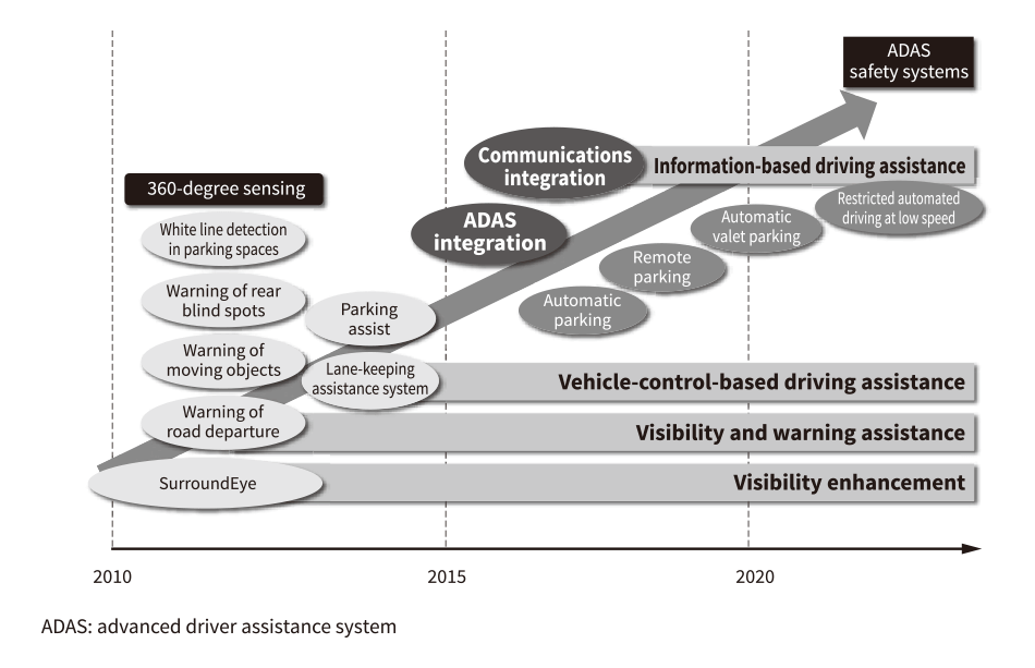
SurroundEye is the name of a function for augmenting the driver's view of the area around the vehicle by synthesizing a single bird's eye view of this area from images captured by cameras mounted on the front, rear, and sides (such as on the front grill, rear bumper, or side mirrors) (see Figure 5).
Already available on the market, SurroundEye has come to be seen as an essential part of the human machine interface (HMI).
Clarion Co., Ltd. has developed a new display format called SurroundEye 3D View, and a warning/assistance system that uses SurroundEye image recognition techniques to perform 360-degree sensing of the surrounding area to detect moving and other objects. The latter system is intended to meet demand from the automotive camera market for providing better visibility. A contribution has also been made to intelligent parking assist (IPA) systems that use parking space detection in car parks.
Recently, industry, government, and academia have been working on the development of automatic parking systems such as valet parking as well as on automated driving systems to provide the public with safe and secure driving conditions, including a reduction in vehicle accidents.
In addition to working on developments that will facilitate advances in automatic parking systems (such as remote parking) by using communication functions for interoperation with infrastructure, Hitachi also intends, in the future, to consider participating in automated driving systems by expanding the scope of sensing to develop technologies for things like the recognition of lane markings, road signs, and road markings, and for identifying and avoiding collisions with pedestrians at intersections(5).
Figure 5 - SurroundEye Enhancements
 Improvements are planned for the functions and performance of SurroundEye because of its role as a vital sensor for autonomous driving, including use as a system for providing better visibility when parking.
Maps are essential for autonomous driving. For example, information from maps is needed to pre-emptively identify intersections or places where roads diverge or converge so as to determine the correct lane to drive in, and to control vehicle speed based on the nature of the upcoming road (such as the presence of curves or hills). However, to make good use of the map, the vehicle must be able to determine precisely where on the map it is currently located. Unfortunately, position information obtained by the global positioning system (GPS) commonly used on vehicles is only accurate to within a few meters, with additional error arising when GPS signal reception is poor. In order to determine the precise vehicle location under these conditions, Hitachi has developed a technique for estimating vehicle location by comparing information obtained by external sensors against the map (see Figure 6).
The improvement in localization accuracy was demonstrated in trials conducted on a test course. Whereas GPS had an error of about 4 m, the map-matching technique improved accuracy to within about 1 m. In the future, Hitachi plans to investigate using the technique for dealing with sharp corners where lane boundary detection is difficult, and for estimating vehicle movement based on changes in the camera images(6)–(8).
Figure 6 - Combination of Sensing Results and Map-based Lane Boundaries
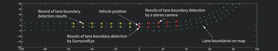 This technique automatically augments vehicle location, using the location of lane boundaries to improve horizontal localization and matching with corner layout to improve localization in the direction of travel.
This article has described the latest work being undertaken to enhance the vehicle periphery sensing techniques needed for autonomous driving.
In the future, Hitachi intends to continue combining these technologies to achieve advances in autonomous driving.
