[ⅰ]Environmental Technologies Contributing to Achieving Carbon Neutrality
Against a backdrop of growing international momentum behind the shift to carbon neutrality, automotive development is one area in which electric powertrains that have less of an impact on the environment are becoming increasingly common. Hitachi is accelerating the development of the electric motors and inverters that are key components of these powertrains, and also developing and deploying the associated technologies required for improving performance. This article describes techniques for achieving high efficiency and output in electric motors and high output density in automotive inverters, and also highly efficient and compact e-Axle technology that uses these components.


The electrification of powertrains for next-generation vehicles is accelerating in countries and regions around the world, primarily in the form of electric vehicles (EVs) and hybrid electric vehicle (HEVs). Internationally, this has included incentives for EVs as well as the announcement of plans to tighten regulation of internal combustion engines (ICEs) or prohibit their sale. In response, several vehicle manufacturers have declared their intention to significantly increase the percentage of their sales accounted for by vehicles with electric powertrains. Progress is also starting to be made on the installation of rapid chargers with support from national and local governments to encourage wider uptake of EVs.
While people are now talking about the possibility of an end to ICEs, this is happening alongside predictions that, even by 2040, more than 75% of vehicles produced will still incorporate an ICE. Amid these predictions of major changes in the market, Hitachi Astemo, Ltd. is accelerating the development of products and technologies for electrification.
This article highlights electric motors and inverters as key components for electrification, describing specific techniques for their use in e-Axle powertrains as well as technologies for efficient electrification products and the high output densities that help reduce carbon dioxide (CO2) emissions.
Key factors in achieving the wider adoption of EVs include the availability of an extensive lineup of electric motors suitable for both small and large vehicles, delivering longer vehicle range and providing motor output and torque characteristics that are tailored to specific vehicle characteristics.
This section presents a lineup of traction motors that are based on the standardized concept of stator and rotor. It also describes the techniques used to achieve high efficiency and output.
Figure 1 — Motor Product Line-up Standardization is being promoted in the range of electric motors in order to meet the diverse requirements for traction motors in a timely manner. This has been accomplished by standardizing on four stator diameters and varying the longitudinal length of the motors to obtain the desired output and torque.
Motor standardization is being pursued as a way to respond promptly to rapidly expanding demand for traction motors. The practice of having standard stator diameters and varying the longitudinal length of the motor to get the desired output and torque has been adopted with the aim of shortening development times. Figure 1 shows the standard motor diameters together with their outputs and target vehicle market segments. The full range of vehicles from small (segment A) to large (segment E) can be covered by motors with standard diameters from 190 to 220 mm.
Figure 2 — Optimization of Stator Coil Specifications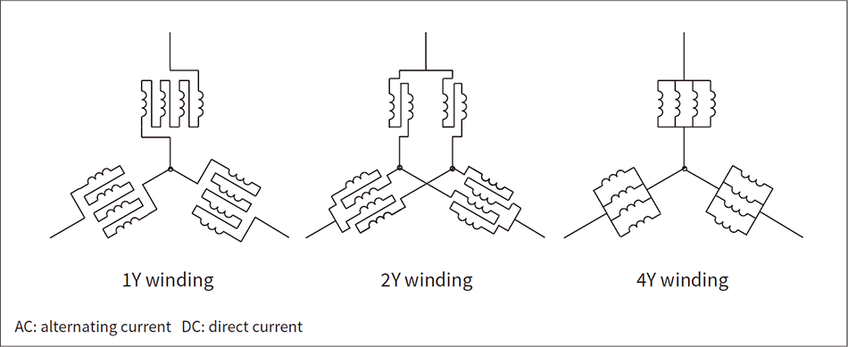 While past practice has been to use either a 1Y or 2Y winding configuration to achieve the best balance of output and torque for different applications, the availability of multi-turn winding opens up a wider range of parallel circuit options, with 4Y windings able to be used to combine high efficiency and output by reducing AC and DC copper loss.
Reducing losses at high speed is an important factor in achieving higher output, with the reduction of alternating current (AC) copper loss in particular being a major issue for motors that use rectangular wire in the stator coil. Multi-turn windings are especially beneficial for this purpose. Changes to the stator coil winding configuration can be used to tailor motors to a wide range of different applications while still maintaining the standard diameter and stator coil geometry. Figure 2 shows the different stator coil winding configurations.
While past practice has been to use either a 1Y or 2Y winding configuration to achieve the best balance of output and torque for different applications, the availability of multi-turn winding opens up a wider range of parallel circuit options. 4Y windings can now be used to combine high efficiency and output by reducing AC and direct current (DC) copper loss. One cause for concern with parallel circuits (such as a 4Y winding) is the presence of circulating currents that result from phase differences between the different circuit branches. This is addressed by adopting a coil layout that minimizes phase difference and simplifies the winding geometry, thereby providing a motor that combines high efficiency and output with low cost.
Automotive inverters convert the DC power stored in the battery to the AC that is used to drive the motor. The motor torque and speed can be varied, and the vehicle speed increased or decreased, by using the inverter to control the amount and AC frequency of the power supplied to the motor. High output density is an important consideration for automotive inverters, which are subject to tight space constraints compared to other applications.
To achieve this desired high output density, Hitachi Astemo has developed a power module with a high level of cooling performance(1). Figure 3 shows how its power module cooling designs have advanced over time.
Direct water cooling has been used since the first-generation inverters. This works by using a fin base to eliminate the thermal grease between the base and fins, thereby reducing thermal resistance. Third generation and later inverters use a double-sided cooling technique that further reduces thermal resistance to 50% of the previous level. This involves full immersion of the power module and has heat dissipation fins on both sides of the power semiconductor.
Whereas most EVs in the past have had a system voltage of approximately 400 V, the current trend is toward 800-V systems with the aim of halving the time it takes to charge the battery. Figure 4 shows the mounting technology developed for insulation and cooling on 800-V systems(2).
Hitachi Astemo has also developed an insulating sheet that can withstand 800 V while still keeping the same thermal resistance as before. This is achieved by means of a laminated structure in which internal conductive foil acts to reduce the voltage across any air voids present in the insulating sheet.
Figure 3 — Advances in Power Module Cooling Design (Cross-section)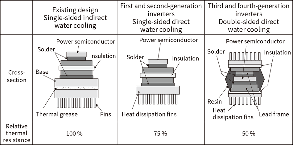 Since its first-generation inverters, Hitachi Astemo, Ltd. has adopted a technique that uses direct water cooling of the fin base, without the need for thermal grease in the power module. Since then, it has developed a double-sided cooling technique that has a fin base on both sides of the chip for enhanced cooling performance. This technique is used in third generation and later inverters.
Figure 4 — Mounting Technology for Insulation and Cooling for 800-V Systems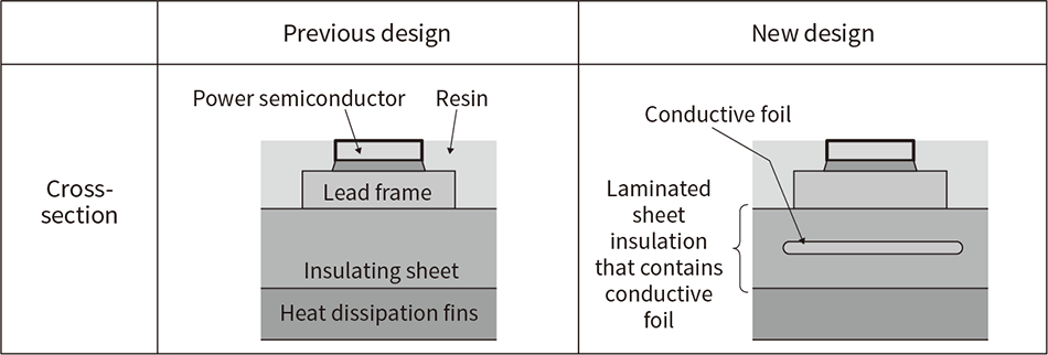 Although the insulating sheet is in contact with the lead frame and heat dissipation fins, tiny air voids form when these parts are joined. Hitachi has developed a laminated sheet insulation containing conductive foil that reduces the voltage across the air voids present in the insulating sheet, allowing it to be used in 800-V systems while still keeping the same thermal resistance as before.
Figure 5 — Automotive Inverter Roadmap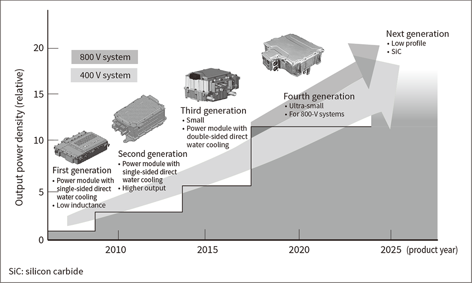 Hitachi Astemo has increased the output power density of its inverters through improvements in power module cooling performance. To allow for 800-V systems, mounting technology for insulation and cooling that can handle high voltages has also been developed for its fourth-generation models.
Figure 5 shows Hitachi Astemo’s roadmap for automotive inverters. Inverter output density has been increased by improvements to power module cooling performance, by reducing the losses of the insulated-gate bipolar transistor (IGBT) power semiconductors, and through the miniaturization of non-power-module components. This miniaturization has included the use of application-specific integrated circuits (ASICs) to reduce circuit board size. As a result, Hitachi Astemo’s fourth-generation inverters have approximately 10 times higher output density compared with the first-generation models. Furthermore, 800-V systems have been made possible by the development of laminated sheet insulation that contains conductive foil.
Meanwhile, the next generation of inverters will have a lower profile for use in e-Axle units that integrate an electric motor, inverter, and gearbox. They will also use silicon carbide (SiC) power semiconductors that feature lower losses than IGBTs.
Figure 6 — Rotor Geometry for High-speed Operation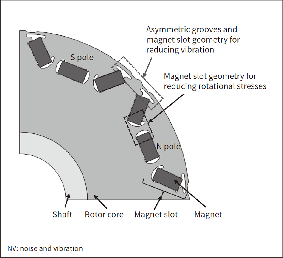 The strength and NV characteristics of the rotor have been enhanced by enlarging the inner and outer end sections of the slots where the magnets are housed.
Figure 7 — Rotor Strength Testing (Spin Test)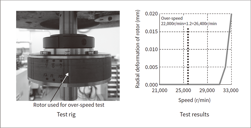 The rotor was turned at high speed to measure its strength. The test found no rotor deformation at the defined over-speed condition (22,000 r/min x 1.2).
The motor, inverter, and gearbox components that make up an e-Axle system need to be made smaller to free up space in the vehicle and to provide more flexibility over where the system can be installed. The power output of a motor is obtained by multiplying torque by speed, with the torque being roughly proportional to motor size. This means that, when designing a motor, the motor can be made smaller by increasing its speed and thereby reducing the torque required to achieve the desired output. This higher speed in turn requires a greater gear ratio to achieve the axle torque, meaning a larger gearbox. Given that motor speeds in the range of 20,000 to 25,000 r/min are ideal for minimizing the overall size of an e-Axle unit, Hitachi Astemo has developed a small, high-speed electric motor with a maximum speed of 22,000 r/min.
As a faster motor needs the strength to withstand the centrifugal force, which scales with the square of angular velocity, as well as measures for dealing with greater noise and vibration, Hitachi Astemo devised a rotor geometry that overcomes these obstacles (see Figure 6).
One feature of this rotor is the enlargement of the inner end sections of the slots where the magnets are housed. This enables a greater radius of curvature, increasing the strength of the rotor core by preventing the concentration of stresses. A second feature is the enlargement of the outer end sections of the magnet slots in the region near the center of the magnetic pole. Grooves are also formed on the outer circumference of the rotor, with the shapes of these grooves being asymmetric with regard to the north and south magnetic poles. The effect of these is to reduce the higher harmonics in the flux density between rotor and stator that are a source of vibration and noise.
The results of calculating the electrical characteristics of a motor fitted with the new rotor indicated that it would achieve its development targets of 155-Nm maximum torque and 120-kW maximum output. Likewise, torque ripple, one of the factors in vibration and noise, was estimated to be 4.5 Nm or less over the entire operating range. Similarly, a strength analysis found that, under over-speed conditions (22,000 r/min × 1.2), the maximum principal stress remained within the material’s yield stress.
An over-speed spin test was also conducted to measure the actual rotor strength characteristics (see Figure 7).
This spin test found no indication of rotor deformation even at speeds in excess of that used to represent an over-speed condition. This verified that the strength of the new rotor could be secured. Meanwhile, load testing conducted to measure the electrical characteristics of the motor verified that its speed-torque curve matched the design values.
This work provided experimental verification of the successful development of a motor with a rotor geometry designed for high-speed operation, and demonstrated that it achieved the desired electrical and strength characteristics.
Higher motor speeds mean higher frequency sinusoidal drive currents. If the switching frequency remains the same as before, this in turn means fewer switchings for each current cycle, causing torque ripple due to the consequent increased distortion in the current waveform. As the associated vibration propagates to the e-Axle’s inverter and gearbox, it has the potential to produce considerable vibration and noise should the frequency of the torque ripple match the natural resonant frequency of any of these components. Accordingly, some means is needed to suppress this noise and vibration (NV). In response, Hitachi has developed a carrier phase shift control technique for reducing NV when the ripple frequency matches the natural frequency.
The causes of motor vibration include both torque ripple due to the motor geometry and torque ripple due to distortion in the current waveform. As shown in Figure 8, whereas torque ripple due to the motor geometry increases in proportion with motor speed, occurring at harmonics such as the 6th (6f1) and 12th (12f1), torque ripple caused by distortion in the current waveform occurs at frequencies associated with the switching frequency (fc±3f1, 2fc) (where f1 is the fundamental frequency and fc is the switching frequency). This makes it difficult to use the two forms of torque ripple to cancel one another out. To overcome this by getting the two ripple frequencies to align, Hitachi Astemo has adopted a technique whereby the switching frequency (fc) for pulse width modulation (PWM) is varied based on the motor speed so as to maintain the desired ratio (9 or 15, for example) between f1 and fc. The difficulty here is that, if the two forms of torque ripple are in phase, they will reinforce one another rather than canceling out. Hitachi Astemo has addressed this by focusing on the phase of the triangular carrier wave used in the inverter. By doing so, it has developed a technique that phase-shifts the carrier wave so as to ensure that the two forms of torque ripple have opposing phases (see Figure 9). When used on a high-speed motor operating at 19,500 r/min (f1 = 1,300 Hz), the technique was able to reduce vibration at the 12th harmonic by 53% while maintaining steady drive performance without generating low-frequency current ripple(3).
Figure 8 — Torque Ripple Frequencies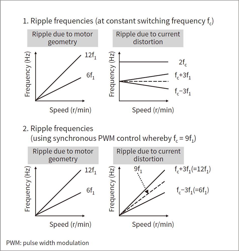 The frequencies of torque ripple due to motor geometry and torque ripple due to current distortion are kept by increasing the switching frequency in proportion with motor speed.
Figure 9 — Overview of Carrier Phase Shift Control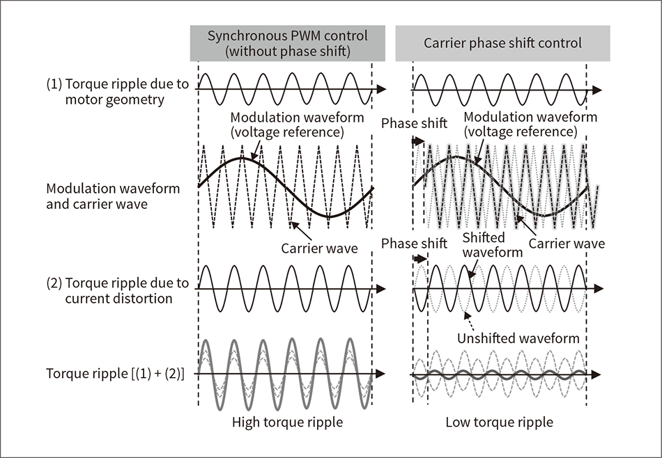 Torque ripple is reduced by phase-shifting the carrier wave in such a way that the torque ripple due to current distortion (2) and the torque ripple due to motor geometry (1) have opposing phases.
This article has described the electric motors and inverters that are key components of EVs as well as the associated technologies required for achieving higher performance.
The aim for the future is to work toward carbon neutrality across all areas of society, including charging infrastructure as well as vehicles. In doing so, Hitachi intends to contribute to society through the further enhancement of these components.
