As technological development progresses, so does the severity of environmental concerns. Electrical and electronic devices are no exception, and there is strong demand for measures against the harmfulness of substances that are used in electronic components and disposed of in large quantities. One representative initiative is the European Union’s RoHS directive, which started restricting the use of specific hazardous substances. The analysis of specific hazardous substances has had a huge impact on manufacturing and quality assurance sites that previously were not responsible for such work. At manufacturing sites, an analysis process was introduced to identify the hazardous substances contained in parts. This analysis was completely different from the normal tasks of the site, resulting in mistakes, inefficiencies, and other issues. Focusing on the fact that specific hazardous substances were targeted for analysis, Hitachi is working on developing dedicated testing equipment based on their conventional analyzers that were optimized for ease of use and operability. This article describes quick and easy testing solutions for environmentally regulated substances to facilitate green innovation.


Table 1 — Each Substance Regulated by RoHS Directive and Regulated Concentration Under the European Union (EU) Restriction of the Use of Certain Hazardous Substances in Electrical Equipment (RoHS) directive, six substances (Cd, Pb, Hg, Cr6+, PBB, PBDE) were regulated from 2006, and four phthalate ester types (DEHP, BBP, DBP, DIBP) were added from 2019.
Recent years have seen huge growth in the production of electrical and electronic devices due to technological development, but this has also resulted in the serious issue of the disposal of these devices. Manufacturing products in a manner considerate of the global environment is extremely important for sustainable economic development. In the European Union (EU), the Restriction of the Use of Certain Hazardous Substances in Electrical Equipment (RoHS) directive (Directive 2002/95/EC) was announced in February 2003, and these regulations on the use of specific hazardous substances were applied from July 2006. A greatly revised version (Directive 2011/65/EU) was announced in July 2011 and applied from January 2013. The revised RoHS directive (RoHS 2) resulted in the addition of four phthalate ester types as regulated substances from July 2019.
Table 1 shows each regulated substance and its regulated concentration. In the USA as well, the Toxic Substances Control Act (TSCA) was passed to prevent hazardous chemical substances from posing a risk to human health or the environment. As an amendment to this Act in January 2021, it was announced that five new persistent, bioaccumulative, and toxic (PBT) chemicals would be added to the regulated substances.
These global trends toward regulating more substances mean that products must be produced in an environmentally conscious way, from development and manufacturing to sales. Furthermore, preparing for these regulatory changes is important to avoid the loss of business opportunities.
Hitachi High-Tech Science Corporation has been developing, manufacturing, and selling a wide variety of analyzers for many years. In response to the recent trend toward stricter substance regulations, the company is providing testing equipment and analyzers for specific hazardous substances that apply the technologies it has cultivated during analyzer development. For RoHS 1, Hitachi High-Tech Science developed an inductively coupled plasma optical emission spectrometer (ICP-OES) for precision analysis and an ultra violet-visible/near infrared spectrophotometer (UV-Vis/NIR) for identifying hexavalent chromium, as well as an energy dispersive x-ray fluorescence (ED-XRF) spectrometer as a screening device. Advantageous features of ED-XRF, including the fact that it eliminates the need for preprocessing to prepare for measurement, resulted in its wide adoption. However, the company proposed a screening device to make the device easier to use so that inexperienced analysts can use it. This concept was continued in the thermal desorption mass spectrometry (TD-MS) testing device for the phthalate esters that were added under RoHS 2.
This section describes the quick testing and analysis technologies that Hitachi has developed to prepare for the expansion of regulations for specific hazardous substances (see Figure 1).
Figure 1 — Analyzers for Substances Regulated by RoHS Directive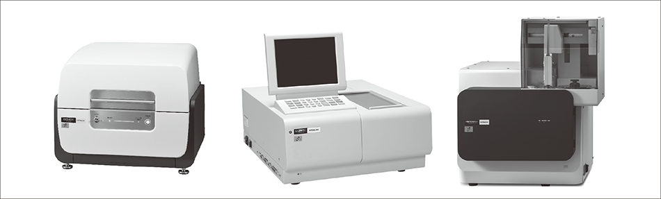 The figure shows EA1400 X-ray fluorescence analyzer (left), U-2900 spectrophotometer (center), and HM1000A screening device for phthalate esters (right).
Figure 2 — Overview of Sample, Irradiating X-rays, and Sample Observation Camera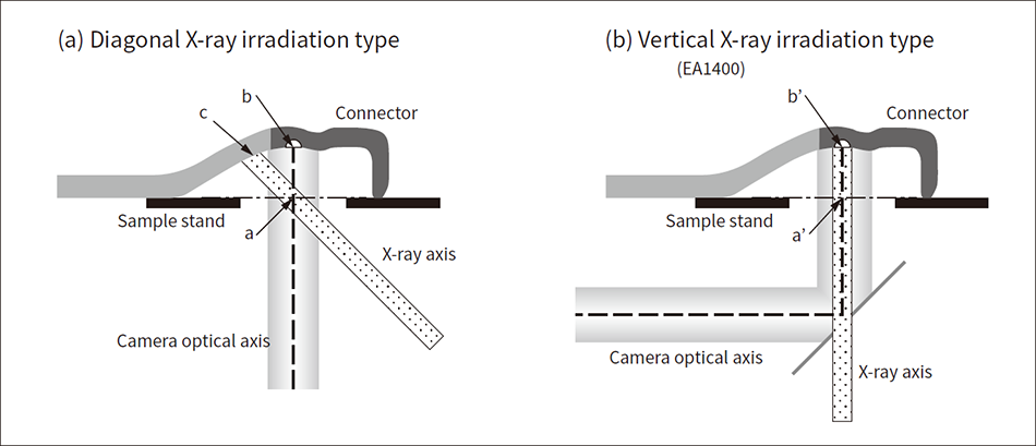 The figure shows the measurement location and X-ray irradiation position in each case of (a) diagonal X-ray irradiation type and (b) vertical X-ray irradiation type.
Figure 3 — Detection Efficiency to Energy Characteristics of Detector and X-ray Fluorescence Spectra of Brass Figure (a) shows a comparison of the detection efficiency between the conventional detector and the new detector, and (b) shows the X-ray fluorescence spectra of brass.
Figure 4 — Procedures of Analysis Method (Conventional Method) and New System (This Method) Based on IEC 62321-7-1 “Hexavalent Chromium – Presence of Hexavalent Chromium (Cr(VI)) in Colorless and Colored Corrosion-protected Coatings on Metals by the Colorimetric Method”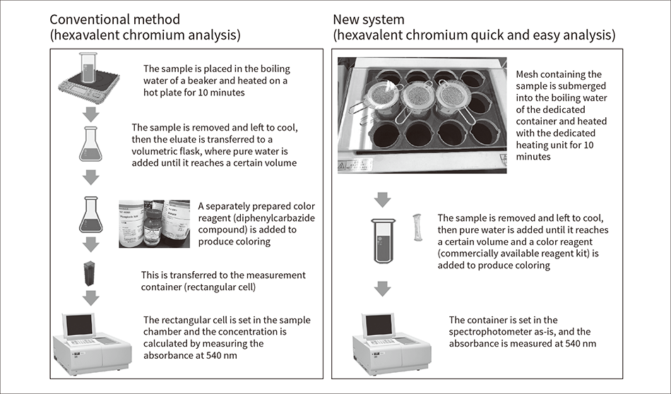 Samples are heated in water for extraction, and the hexavalent chromium concentration is calculated from the absorbance at 540 nm of the colored solution.
International standard IEC 62321-3-1(1) standardizes the screening analysis methods for lead, mercury, cadmium, total chromium, and total bromine using X-ray fluorescence spectrometry. The X-ray fluorescence analysis is a technique for obtaining information about the type (qualitative) and quantity (quantitative) of elements in a sample by irradiating it with X-rays and then detecting the characteristic X-rays emitted from the elements contained therein. This testing method is easy because it does not require preprocessing and enables non-destructive and non-contact analysis. For this reason, it has been widely adopted for applications such as product shipment testing, failure analysis, and material acceptance testing(2). A particular advantage can be seen for underside irradiation types of devices where the sample is irradiated by X-rays from below, because the heights of the irradiating X-rays and the sample do not need to be adjusted, enabling measurement to be started after simply setting the sample. This has resulted in such devices becoming the mainstream testers for environmentally regulated substances.
However, several issues remain for samples with complex shapes, such as connectors. The first is that the actual X-ray irradiation position deviates from the target position identified with the sample observation camera.
Figure 2 shows the positional relationships between the sample, irradiating X-rays, and sample observation camera when measuring a connector with an underside irradiation type of X-ray fluorescence analyzer. Analyzers can be broadly divided into two types according to their X-ray irradiation angle: the diagonal irradiation type that irradiates diagonally relative to the sample [see Figure 2 (a)] and the vertical irradiation type that irradiates vertically [see Figure 2 (b)].
The diagonal irradiation type is designed so that the irradiating X-rays and the camera optical axis intersect at the position of the sample stage (point a). For this reason, when the measurement location is in a position separated from the sample stand like on a curved connector, the camera optical axis passes through the measurement location (point b), but the irradiating X-ray axis passes through a position outside the measurement location (point c). Therefore, a location is tested that is different from the position identified with the camera. In this case, it is necessary to either stretch the curved section or cut off the excess part, etc. This eliminates the advantages of the X-ray fluorescence analyzer; namely, non-destructive measurement with no preprocessing.
In response, a vertical irradiation method like the one shown in Figure 2 (b) has been adopted for the latest EA1400 X-ray fluorescence analyzer. Furthermore, a coaxial observation mechanism that ensures the irradiating X-rays and sample observation camera optical axis are along the same axis was adopted, enabling measurement with no deviation from the target position of the irradiating X-rays and camera optical axis even at a position separated from the sample stage (point b’).
The second issue is the decreased intensity of the detected X-ray fluorescence due to the distance between the detector and measurement location. Since the detector in an underside irradiation type of device is lower than the sample stage, when the measurement location is separated from the sample stage, the distance between the detector and sample is also longer, resulting in decreased intensity of the detected X-ray fluorescence. In response to this issue, the EA1400 has been equipped with a new type of high-sensitivity, high-resolution semiconductor detector (silicon drift detector) to provide improvements over conventional devices. A feature of semiconductor detectors is their high energy resolution, and the thickness of the elements has been doubled in the new detector, which increases not only the detection resolution, but also the detection sensitivity. As a result, even when the measurement location is separated from the sample stage, more intense X-ray fluorescence than before can be obtained.
Figure 3 (a) shows the detection efficiency relative to energy levels, comparing the new detector to the conventional detector. This demonstrates that the detection efficiency has been improved over a wide energy range; in particular, efficiency is almost doubled in the high energy bands. This dramatic improvement of sensitivity in the high energy bands is expected to enable effective measurement not only of cadmium, but also of tin and antimony, which may be added to the regulated substances in the future. Figure 3 (b) shows the X-ray fluorescence spectra after measuring the cadmium in brass, which is frequently used in parts such as connectors. An improvement in sensitivity to more than double the level of conventional models has been confirmed in the EA1400 equipped with the new detector.
Adding these improvements enables easy screening analysis of environmentally regulated substances using the X-ray fluorescence analyzer, even for samples with complex shapes.
When chromium is detected in the screening of X-ray fluorescence analysis, its valence cannot be identified by X-ray fluorescence analysis. Therefore, whether or not the chromium is the regulated hexavalent chromium must be determined using a spectrophotometer.
Figure 4 shows the procedures of the analysis method (conventional method) and new system (this method) based on IEC 62321-7-1 “Hexavalent chromium – Presence of hexavalent chromium (Cr(VI)) in colorless and colored corrosion-protected coatings on metals by the colorimetric method.” In the conventional method, all processes per 10 samples take about 50 minutes, with an actual work time of about 30 minutes.
Preprocessing is complicated and preparation of color reagents is also required. Furthermore, when a sample is placed inside boiling water heated on a hot plate, some areas of the sample directly touch the heating unit, resulting in a difference between the states extracted from the boiling water. Also, when the sample amount satisfies the specified sample surface area of 50 cm2, since multiple samples are placed into a single extraction container, errors occur from the difference in time that they are in the boiling water. This analysis requires expert skills, but in the more than 10 years since the regulations came into effect, it has become apparent from issues such as revisions to operational systems, generational engineer turnover, and shortages of analysis engineers, that a quick and easy analysis method with minimal error is necessary. This is the reason behind the development of the new system described in this article.
All the processes in this method’s procedure take about 25 minutes and the actual work time is about 10 minutes, resulting in expected labor savings of 50% or more.
The samples in this method are placed in a dedicated mesh, which is then submerged in boiling water. This minimizes any difference in sample insertion times and prevents any part of the samples from directly touching the heating unit, enabling extraction at a uniform boiling water temperature and minimizing extraction errors(3). Also, to check temperature differences due to the container installation locations, the evaporation amount of the boiling water was evaluated while the container was installed in different locations: the hot plate and the heating unit. After measuring the weight at 90°C before heating, the beaker was covered with a watch glass and the water was boiled. After boiling, the watch glass was removed and the water was further heater for 10 minutes. Then, the total weight of the beaker and boiled water was measured and the amount of decrease was calculated. In the case of the hot plate, the amount of decrease varied greatly according to the location, with a difference of 53% in the coefficient of variation (CV) that expresses the location-based relative variation.
The difference in the amount of water decrease was especially large between a beaker installed on the outer side and a beaker installed at the center. In the case of the dedicated heating unit, the difference between the maximum and minimum was small, with a CV of about 4% (see Table 2). This demonstrated that there was almost no difference in the evaporation amount according to the installation location, and the heating unevenness was low. Therefore, using this system makes it easy to ensure extraction accuracy. The dedicated heating unit securely holds each individual heating extraction container, eliminating any risk of knocking over a heated container and contributing to safety.
By using a dedicated holder for the spectrophotometer, a good calibration relationship was confirmed for this method as well. The sensitivity has also been increased because the dedicated container has a long optical path. Since the container is cylindrical, the absorbance was measured at each of the four orientations of 0, 90, 180, and 270 degrees to identify errors. The results showed that the error within a container is about 1 to 3 % and the error between containers is about the same at 1 to 3 %.
This method: (1) enables stable extraction, (2) makes transferring of solution unnecessary, (3) makes work very safe, and (4) automatically calculates the concentration. Therefore, stable operations are possible even if the analysis technicians do not have expert skills.
Table 2 — Changes in Boiling Water Evaporation Amount between Hot Plate and Dedicated Heating Unit The same container is installed in five locations for each heating method and the amount that the boiling water decreases in 10 minutes is measured.
Figure 5 — Device, Overview of Measurement Principle, and Example of Mass Spectra for Phthalate Esters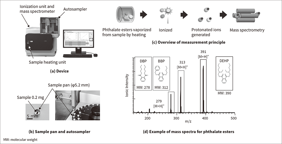 The figure shows the device (a), a sample pan and an autosampler (b), an overview of the measurement principle (c), and an example of mass spectra for phthalate esters (d).
The phthalate esters that were added as regulated substances by the revision of the RoHS directive (see Table 1) are used as plasticizers and added to give flexibility to materials such as resin and rubber. In particular, they are frequently used in polyvinyl chloride products such as cable coverings, electrical insulating tape, and wrapping film. Companies must now identify and manage the phthalate ester content in their products, parts, and other materials. Phthalate esters are well known as substances that transfer their properties through physical contact, requiring even stricter control than in the past.
The official method for measuring phthalate esters is solvent extraction and gas chromatography-mass spectrometry. However, this method has several issues; for example, the process takes time because component extraction using an organic solvent is necessary, and expert knowledge is required because of the complex devices that use a large volume of solvent. Thermal decomposition and gas chromatography-mass spectrometry simplifies preprocessing of the sample but issues remain, such as the analysis time of about 30 minutes that it takes for each sample and the specialist knowledge that is required to analyze the results. Therefore, this method is not appropriate for easy testing at production sites.
Hitachi High-Tech Science developed the HM1000A thermal desorption mass spectrometer as a quick and easy testing device for phthalate esters(4).
Figure 5 (a) shows the device appearance. The device consists of a sample heating unit that vaporizes the phthalate esters from the sample, an ionization unit that ionizes the vaporized phthalate esters, and a mass spectrometer that analyzes the ionized components. Also, an autosampler enables continuous and automatic measurement for up to 50 samples.
The samples are cut to an appropriate amount (about 0.2 mg) and set in a dedicated sample pan [see Figure 5 (b)]. Figure 5 (c) shows an overview of the measurement principle. When measurement starts, the autosampler takes up the sample pans one by one and feeds them to the sample heating unit. The sample is heated on the heating unit to vaporize the phthalate esters. The vaporized phthalate esters are ionized by the ionization unit and the mass is analyzed by the mass spectrometer. The ionization method is atmospheric pressure chemical ionization (APCI), which uses a corona discharge generated by applying voltage to a discharge needle. The molecules are protonated to ionize the vapor. A characteristic of the APCI method is its low incidence of fragmentation, which refers to the cleavage of molecular bonds. Ionization can be performed without destroying the molecular structure, enabling direct mass spectrometry.
Figure 5 (d) shows an example of mass spectra obtained by the HM1000A for 1,000 mg/kg of dibutyl phthalate (DBP), benzyl butyl phthalate (BBP), and di-2-ethylhexyl phthalate (DEHP), which are all phthalate esters. It was confirmed that the protonated ions of m/z279, (DBP), m/z313 (BBP), and m/z391 (DEHP) could be detected for each.
Feeding the gas vaporized from the sample directly into the mass spectrometer without separating its components enables quick testing of 10 minutes per sample. The autosampler can be used to perform continuous and automatic measurement for up to 50 samples, including standard substances, in about 8 hours. The user can perform continuous measurement simply by executing a preset recipe to obtain the screening judgment results for each sample. Therefore, the presence of phthalate esters can be determined without the need for specialist knowledge.
Short throughput is required in the screening, but even when measurement is performed in a short time, if the detection capacity of the device is insufficient, then the result will be “Judgment not possible” for many samples. In this case, the device user must redo precise analysis for the samples that generated the “Judgment not possible” result to confirm the judgment results. In other words, the increase in the number of samples that cannot be judged by screening leads to an increase in time and costs until the judgment results are obtained, which makes screening pointless. This device achieves detection at a lower limit of 100 mg/kg or less, which is sufficient for the phthalate ester regulation value of 1,000 mg/kg under the RoHS directive. Figure 6 shows the ionic intensity profiles for samples with the different phthalate ester content concentration. The measurement samples were 0 mg/kg, 100 mg/kg, and 500 mg/kg of a standard solution mixed with phthalate esters dropped into a polyvinyl chloride (PVC) solution, and then the samples were removed and dried at room temperature. The horizontal axis of the graph represents the time from the start of measurement, and the vertical axis represents the ionic intensity of each phthalate ester. It was demonstrated that when the content of each phthalate ester is 100 mg/kg, the peaks can be clearly identified.
This device can also perform qualitative analysis of decabromodiphenyl ether (Deca-BDE), one of the polybrominated diphenyl ether (PBDE) specific brominated flame retardants regulated under the RoHS directive whose contamination is a particular risk. After total bromine is detected in samples in screening with the X-ray fluorescence analyzer, measuring with this device can be utilized as an easy secondary screening method for identifying whether the samples contain Deca-BDE.
Figure 6 — Ionic Intensity Profiles for Various Phthalate Ester Concentrations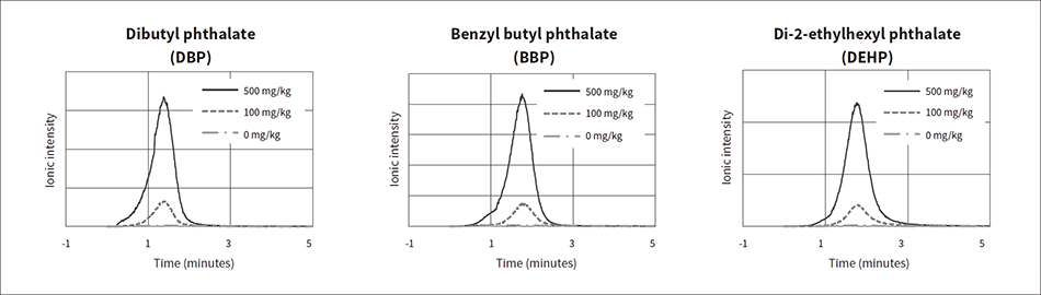 The following shows the measurement results after dropping 0 mg/kg, 100 mg/kg, and 500 mg/kg of a standard solution mixed with phthalate esters into a polyvinyl chloride solution, and then drying the sample.
As previously described in this article, when managing environmentally regulated substances, different analyzers must be used according to component to be tested. When a company has many production sites worldwide and each stores its test results in different analyzers, the test results cannot be accessed quickly, resulting in commensurate costs for operation and management. Hitachi High-Tech Science has developed the cloud-based “ExTOPE” system, which automatically uploads the test results obtained from multiple devices across multiple worksites to provide centralized management that helps make management more efficient.
Testing for specific hazardous substances has continued for more than 15 years since the EU’s RoHS directive was enacted in 2006(5). During this period, usage restrictions for specific hazardous substances have expanded, requiring ever more efficient testing at worksites. These usage restrictions for hazardous substances have changed conventional device paradigms, leading to the development of dedicated devices that standardize preprocessing and measurement processes to obtain measurement results that are not affected by the skill or experience level of the operator. Furthermore, to enable the stable management of testing work for hazardous substances that is conducted at a wide variety of manufacturing sites, utilization of ExTOPE is being promoted for the centralized management of device states and measurement results across multiple sites. This makes management more efficient in a manner independent of time or place. To ensure compliance when developing various products, it is very important to test the used materials for their hazardous substance content and to perform these tests quickly.
In the future, Hitachi High-Tech Science will continue to devise solutions that provide information proving that the materials used in electrical and electronic products do not contain specific hazardous substances in a quick and easy manner that is demanded by the market.
