In response to issues encountered after the Great East Japan Earthquake, projects are underway to expand the grid interconnection capacity between the different frequencies in eastern Japan (50 Hz) and western Japan (60 Hz). In April 2019, Hitachi, Ltd. received an order from Chubu Electric Power Grid Co., Inc. for the delivery of two blocks of frequency converter system at the Higashi-Shimizu Substation and for services such as equipment installation and testing. The aim is to start operation by the end of FY2027, with the interconnection capacity increased from the current 300,000 kW to 900,000 kW. The core equipment in this system, an AC-DC converter, will be the first back-to-back frequency converter in Japan to apply voltage source converter (VSC) technology. This new technology enables a black start that supplies power even when there are power failures during large-scale natural disasters, and the independent control of the active power and reactive power of the power grid. The technology is expected to be effective for stabilizing the power system. This article describes an overview of the project and the converter.

High-voltage direct current (HVDC)*1 power transmission systems are attracting attention worldwide as a solution that supports the expansion of renewable energy as a main source of electric power, thus helping to achieve a decarbonized society. HVDC not only improves the resilience of the existing grid, but also has such advantages as reducing power transmission loss compared to alternating current (AC) systems, and enabling construction in a short period of time using techniques such as undersea cables. As a result, in Europe, which has been a pioneer in the large-scale deployment of offshore wind power and other renewable energy sources, cost-benefit analyses and other reports have shown many cases where the economic rationality of strengthening interconnection using HVDC is superior to using AC systems. This technology has benefitted from large-scale investment, leading to an HVDC market that is booming like never before.
Hitachi has been involved in nearly all HVDC projects in Japan since the development of HVDC in 1970. The year 2015 was a major turning point as Hitachi established Hitachi ABB HVDC Technologies, Ltd. as a joint venture with the power grids business of the Swiss-Swedish electrical engineering conglomerate, Asea Brown Boveri (ABB) Ltd. (what is now Hitachi Energy Ltd.) in order to expand HVDC business in Japan. The business has since been renamed Hitachi HVDC Technologies, Ltd. The company has steadily built up a record of achievements in Japan, and in 2021, through a joint venture, it delivered Japan’s first overseas-made air-insulated filter for HVDC systems to the Hida Converter Station of Chubu Electric Power Grid Co., Inc.
The Great East Japan Earthquake on March 11, 2011, resulted in large-scale power loss in areas supplied by power companies in the Tohoku and Kanto regions. However, the amount of power interchange from power companies in other areas was limited due to restrictions in the interconnection capacity. This meant that rolling blackouts became unavoidable in some areas of the Kanto region. In view of this experience, the Organization for Cross-regional Coordination of Transmission Operators (OCCTO), Japan, which supervises power interchanges between power companies, identified the enhancement of grid interconnection capacity to achieve wide-area grid operations that go beyond the borders of individual areas as the most important challenge that they faced. Projects are underway for enhancing the interconnection capacity between the 60 Hz Chubu Electric Power Grid area and the 50 Hz area from the initial 1.2 million kW*2 to 3 million kW. The Higashi-Shimizu Substation was selected as one of the frequency converters (FCs) to enhance, and facility owner Chubu Electric Power Grid was selected as the entity to implement the enhancements. After submitting technical proposals and quotations over a long period from 2017, Hitachi finally received the order in April 2019.
Among the FC facilities, Hitachi was given responsibility for the overall engineering of the system, the design and manufacturing of converter transformers, installation work for equipment, and system integration such as grid interconnection testing. Hitachi Energy is providing the main circuit equipment and control and protection systems, such as the converter valve that forms the core technology of the facilities.
This article describes the features of the main systems delivered by Hitachi, which were optimized according to the unique specifications and conditions of the Higashi-Shimizu Substation.
Figure 1 — Power Grid Near Higashi-Shimizu Substation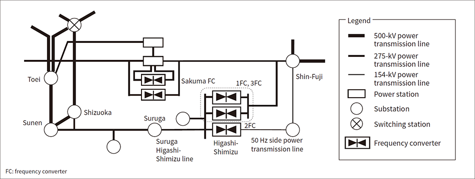 Currently, the 60 Hz side is interconnected with the existing No. 2 FC via the 275-kV Higashi-Shimizu line from the Suruga Substation of Chubu Electric Power Grid, and the 50 Hz side is interconnected with No. 2 FC via the 154-kV power transmission line. This project will construct a new 275-kV power transmission line on the 50 Hz side and interconnect it with the newly-installed No. 1 FC and No. 3 FC.
The Higashi-Shimizu Substation of Chubu Electric Power Grid is located in the Shimizu Ward of Shizuoka City, Shizuoka Prefecture, and is the third substation in Japan to contain FCs.
Figure 1 shows a diagram of the power grid. Currently, the 60 Hz side is interconnected with the existing No. 2 FC via the 275-kV Suruga Higashi-Shimizu line from the Suruga Substation of Chubu Electric Power Grid, and the 50 Hz side is interconnected with No. 2 FC via the 154-kV power transmission line. In this project, a new 275-kV power transmission line will be installed on the 50 Hz side, and this will be interconnected with the newly-installed No. 1 FC and No. 3 FC.
In the approximately four years since receiving the order for this project, Hitachi has made great efforts in various system studies, station layout plans, and finalizing the main circuit specification. Fully fledged engineering and civil construction work started at the substation in 2022. Hitachi has started manufacturing the equipment in 2023, and will install the equipment starting from 2024.
The next section describes an overview of the HVDC system and the features of the main circuit equipment including converter valve and control and protection systems.
Figure 2 — Main Circuit Configuration of Higashi-Shimizu Substation and Newly-installed No. 1 and No. 3 FCs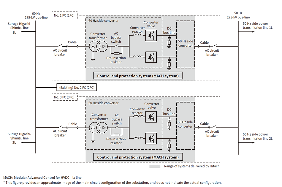 The AC side of each FC is connected from the 275-kV bus-line to the primary side of the converter transformer via a cable, and equipment that forms the AC-DC converter is installed on the secondary side. Each FC is controlled and protected by the MACH system.
Figure 2 shows the main circuit configuration of the Higashi-Shimizu Substation, including the No. 1 and No. 3 FCs that will be newly installed. Both FCs will be connected to the 275-kV bus on the 60 Hz side to the 275-kV bus on the 50 Hz side. Each FC has conversion capacity of 300 MW rated active power and ±100 Mvar rated reactive power, and they are configured as a back-to-back (BTB) system using HVDC Light, Hitachi Energy’s self-commutated*3 converter. Figure 2 shows the main circuit configuration representing the converter on the 60 Hz side, but the same is also used for the converter on the 50 Hz side. The No. 1 FC and No. 3 FC are independent FCs, and each is in a symmetrical monopole configuration. Also, for the 275-kV bus on the 60 Hz side, the existing No. 2 FC is interconnected in parallel (the interconnection to the 154-kV bus-line on the 50 Hz side is omitted from the figure). The scope to be delivered by Hitachi is shown within the shaded area of Figure 2 including the converter transformer and its secondary side (converter side) AC/DC equipment, and the control and protection systems.
The AC bus is connected to the primary side of the converter transformer via an AC circuit breaker and a cable. The converter transformer is composed of Y-Δ windings and the primary side is grounded directly. Converter reactors and converter valves for both the positive and negative poles are connected to the secondary side of the converter transformer via an AC bypass switch and pre-insertion resistor. The DC bus is equipped with a pole capacitor and a DC damping resistor, which maintain the ground potential balance of the positive and negative DC poles while reducing the ripple voltage that accompanies valve switching.
A control and protection system called Modular Advanced Control for HVDC (MACH) is provided for both the No. 1 and No. 3 FCs. It controls apparatuses such as the AC circuit breaker, AC bypass switch, and converter valves, while also controlling auxiliary equipment that is not shown in the figure, such as the valve cooling system.
Figure 3 — Configuration of AC-DC Converter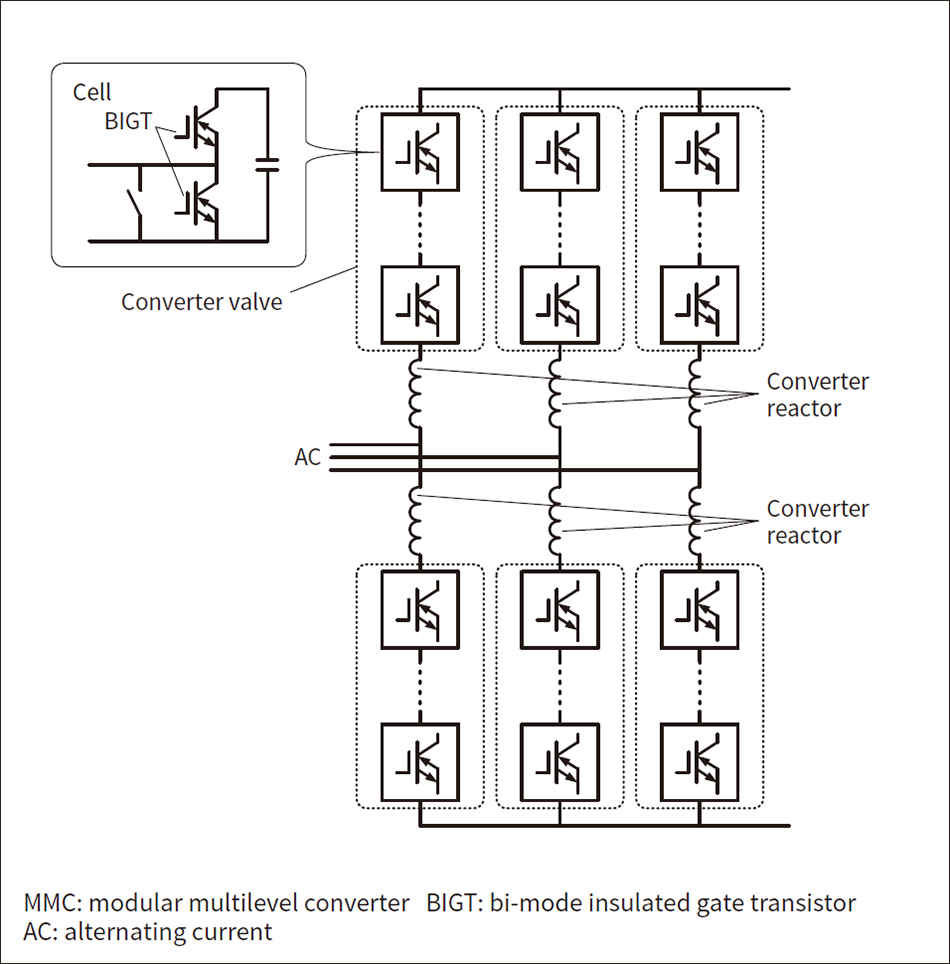 The AC-DC converter has an MMC configuration where each cell is a chopper cell using BIGT.
In this FC, a modular multilevel converter (MMC) is used as the AC-DC converter. Figure 3 shows the configuration and main specifications of the AC-DC converter.
An MMC is an AC-DC converter circuit based on arms composed of identical cells (also called submodules) connected in series. The arms are connected in a three-phase bridge to form the AC-DC converter. A feature of an MMC is its high scalability in terms of capacity and voltage, which can be varied by increasing or decreasing the number of cells. The standard lineup of Hitachi Energy’s HVDC Light supports voltages and capacities up to the ±640-kV class and 4,000-MW class. In this project, factors such as the grid voltage and frequency variations have been considered to design the valve configuration and the main circuit parameters that satisfy the required capabilities of 300 MW and 100 Mvar.
Bi-mode insulated gate transistors (BIGT) of a 5.2 kV withstand voltage are used as the power semiconductor devices in the cells. A BIGT is a semiconductor device that combines the functionality of a conventional insulated gate bipolar transistor (IGBT) and a free-wheeling diode on a single semiconductor chip, and is thus a type of a reverse conducting IGBT. Since the IGBT current and the diode current flow on the same chip, the chip has benefits for balancing heat generation and heat dissipation, making it suitable for higher currents. In this project, two BIGTs are used in each cell to form a chopper cell.
Figure 4 — Example of Analysis of Three-phase Grounding Fault Near Higashi-Shimizu Substation on 60 Hz Side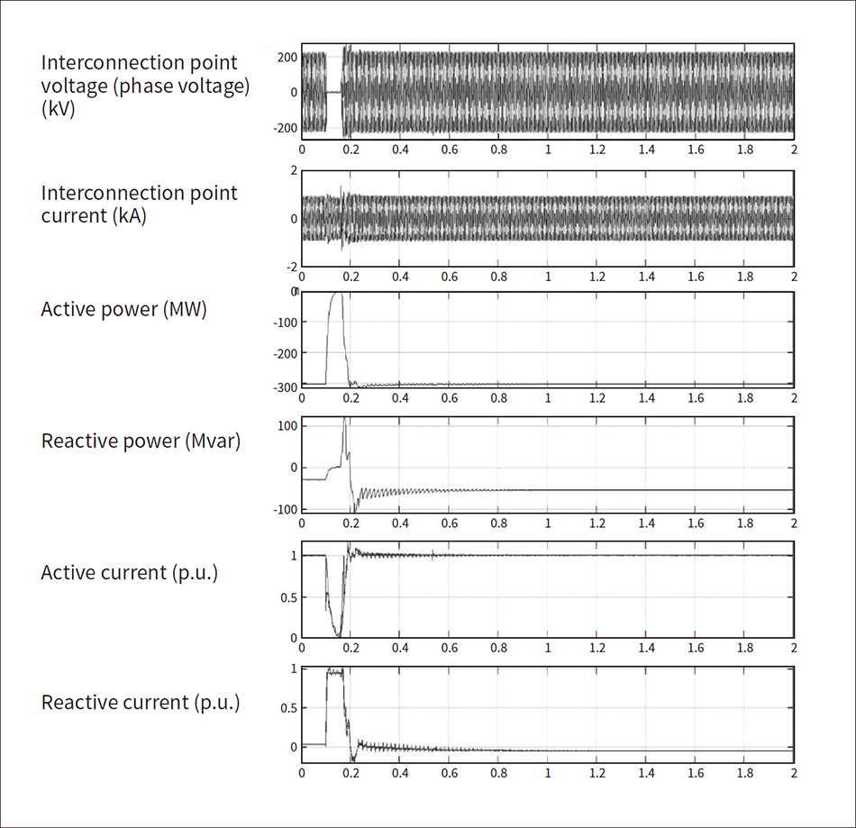 The analysis confirmed that even if a malfunction such as a short circuit or grounding fault occurs on the AC grid side, the converter can continue operation without gate blocking. Also, reactive current is input while the grid failure continues to contribute to power grid stabilization.
Figure 5 — Image of Frequency Converter Building (No. 1 FC, No. 3 FC)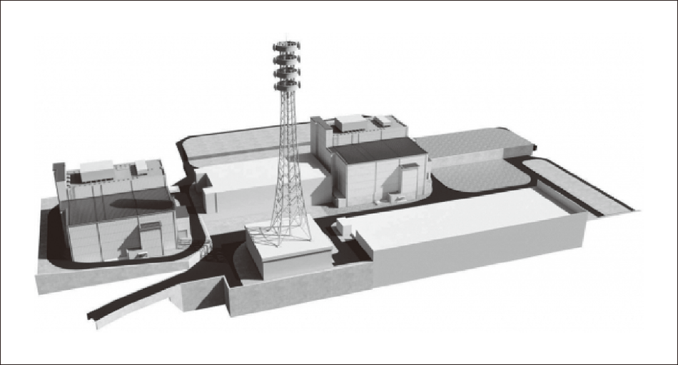 The figure shows the No. 3 FC (left), No. 2 FC (center), and No. 1 FC (right). After completion, the building will have one underground floor and two floors above ground, and the building height will be about 25 m above ground.
A feature of the Higashi-Shimizu Substation is its compact size, located on a steep hillside. Figure 5 shows an image of how the substation will look after the completion of the building construction. The existing No. 2 FC is at the center, with the No. 3 FC newly constructed on the north side and the No. 1 FC on the south side. Due to the limited space at the substation site, it was difficult to devise an efficient equipment layout that maintained the required electrical and maintenance work clearance during a phase where the equipment design had not yet been finalized. Engineering and construction staff collaborated frequently to design a building that would not hinder the actual equipment installation work or the maintenance work after the start of commercial operation.
This article described the No. 1 FC and No. 3 FC at the Higashi-Shimizu Substation whose operation is scheduled to start at the end of FY2027, and the specifications and features of the frequency converters and equipment that will be delivered by Hitachi.
Hitachi positions HVDC as one of its core businesses within the energy field, and in the future, Hitachi will continue to meet demand for grid interconnection facilities that accompany the enhancement of grid interconnection and growth of renewable energy both in Japan and overseas, thus contributing to the achievement of a decarbonized society.
