The stable supply of electric power requires a minimum reserve rate of 3%. However, ever since the Great East Japan Earthquake in 2011, the margin between the supply and demand of electricity in Japan has been tight. When demand for electric power increases due to extremely hot or cold weather and the risk grows of not securing the 3% reserve rate, the authorities issue a power crunch warning or alert. It was in this context that on September 16, 2021, a failure due to aging forced the emergency stop of the unit No. 8 generator step-up transformer (built in 1981) at the Nakoso Power Station of Jōban Joint Power Co., Ltd. This shut down the supply of 600,000 kW of electric power, which is equivalent to about 1% of the total demand peak in the Tokyo area. Hitachi, Ltd. received a request from the customer for the rapid restoration of the power station to help stabilize the power supply in Japan. In a project that would normally take more than a year to deliver from receiving the order to transmitting power, all stakeholders came together as a team to complete the work in about 9 months.
The proportion of Japan’s annual power generation capacity taken up by thermal power generation has decreased steadily since the oil crisis in the 1970s. But since the Great East Japan Earthquake in 2011, the proportion increased as thermal power generation replaced nuclear power generation. Then, the proportion of thermal power started to decrease again as the use of renewable energy expanded and some nuclear power stations were restarted; even so, it still makes up about 70% (about 700 billion kWh) of the power supply in Japan.
Of this 70%, the Nakoso Power Station of Jōban Joint Power Co., Ltd., a complex containing three power generators (unit No. 7 generator: 250,000 kW, unit No. 8 generator: 600,000 kW, and unit No. 9 generator: 600,000 kW) provides an amount of power equivalent to about 1% of Japan’s thermal power generation (7 to 10 billion kWh annually) to the Tohoku and Tokyo areas. However, on September 16, 2021, a failure due to aging forced an emergency stop of the unit No. 8 generator step-up transformer (GSUT) at Nakoso Power Station. This shut down the supply of 600,000 kW of electric power, which is equivalent to about 1% of the total demand peak in the Tokyo area. In response, Hitachi was requested to conduct rapid restoration work to restart the power generation and help secure the reserve rate of 3%.
Figure 1 shows the main circuit configuration around the unit No. 8 GSUT of the Nakoso Power Station that was subject to this restoration project.
After receiving notification about the failure of this transformer, Hitachi quickly dispatched inspectors to the site to investigate the cause of the failure and start considering methods for rapid restoration. Hitachi considered the restoration methods of onsite repair, offsite repair, replacement with a spare from another power plant, or manufacture of a new transformer. Hitachi submitted a report to the customer that detailed the work schedule and various conditions for all of these restoration methods, as well as the results of the cause of failure investigation. After discussing these results together, the customer selected the rapid restoration proposal based on replacing the transformer with one that would be newly manufactured. Hitachi conducted an additional investigation into the cause of failure and considered countermeasures to prevent the same incident from occurring with the new transformer.
Two proposals were considered for where to manufacture the new transformer; at the Hitachi Works Kokubu Factory (Kokubu Factory) or at the Chongqing Factory of Hitachi Energy (China) Ltd. (Chongqing Factory). In this project, since Hitachi received consent from the customer to re-examine some of the existing interfacing parts, the Kokubu Factory was selected because it owns the existing design. Although the Chongqing Factory was not selected due to transportation times and conditions, the high level of its product manufacturing capacity was confirmed, with almost no difference from the Kokubu Factory, even when considering the new design and the manufacturing period for all the new parts.
Hitachi shortened the process while sharing and consulting with the customer about the risks and opportunities inherent in rapid restoration across the entire project, including manufacturing, transportation, and construction work. This enabled Hitachi to complete the project from receiving the restoration instructions to transmitting the power in a very short delivery time of about 9 months (see Figure 2).
This article describes how Hitachi was able to cope with such a short delivery time while ensuring quality and avoiding accidents.
Figure 1 — Schematic Diagram of Nakoso Power Station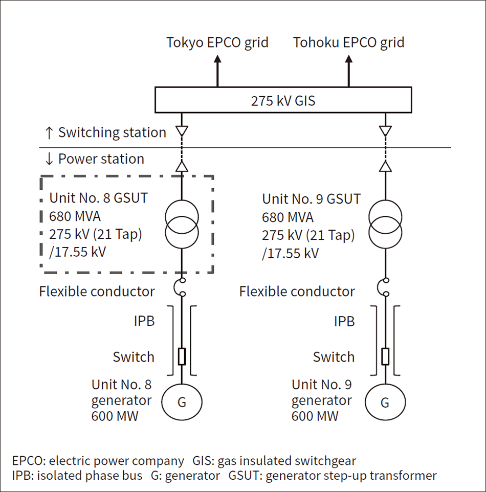 In this project, Hitachi worked toward the rapid restoration of the unit No. 8 GSUT.
Figure 2 — Overview of Restoration Process Results for Unit No. 8 GSUT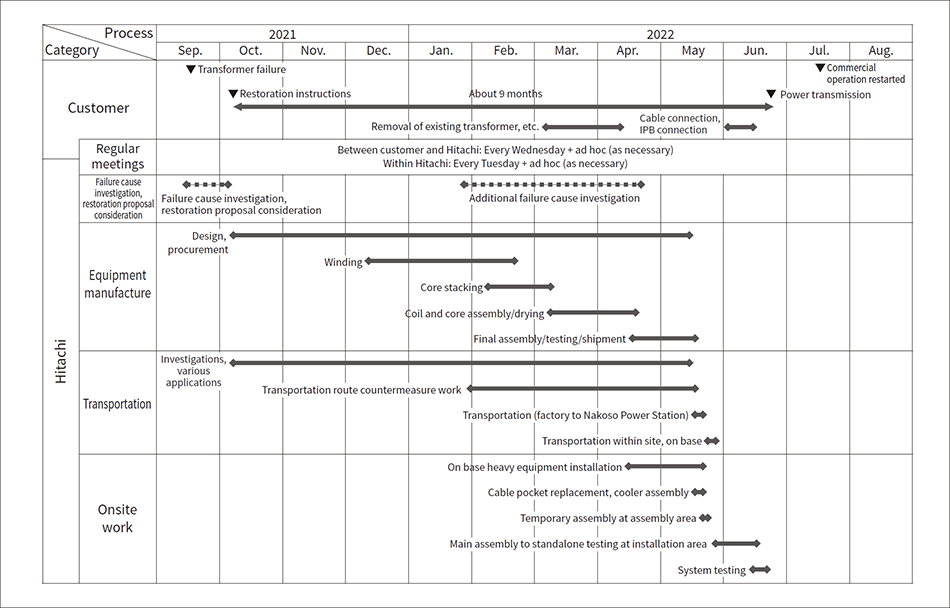 In addition to investigating the causes of the failure immediately after the failure occurred, Hitachi considered various rapid restoration methods and completed the project in about 9 months; normally, the process from receiving the order to transmitting power would take more than a year to deliver.
This section describes the actions Hitachi took to achieve the short delivery time.
Immediately after receiving the restoration instructions, Hitachi appointed its internal project members (from the business unit and design, procurement, manufacturing, quality assurance, transportation, and construction departments) and set up regular meetings (within Hitachi: every Tuesday, between the customer and Hitachi: every Wednesday). This created a system that could confirm the progress of work in a timely manner. Hitachi also held ad hoc meetings if any urgent matters were discovered to ensure actions could be taken without delay to avoid risks (process delay or malfunctions) or to make the most of opportunities (shortening the process).
Figure 3 — Overview of Transformer Manufacturing Flow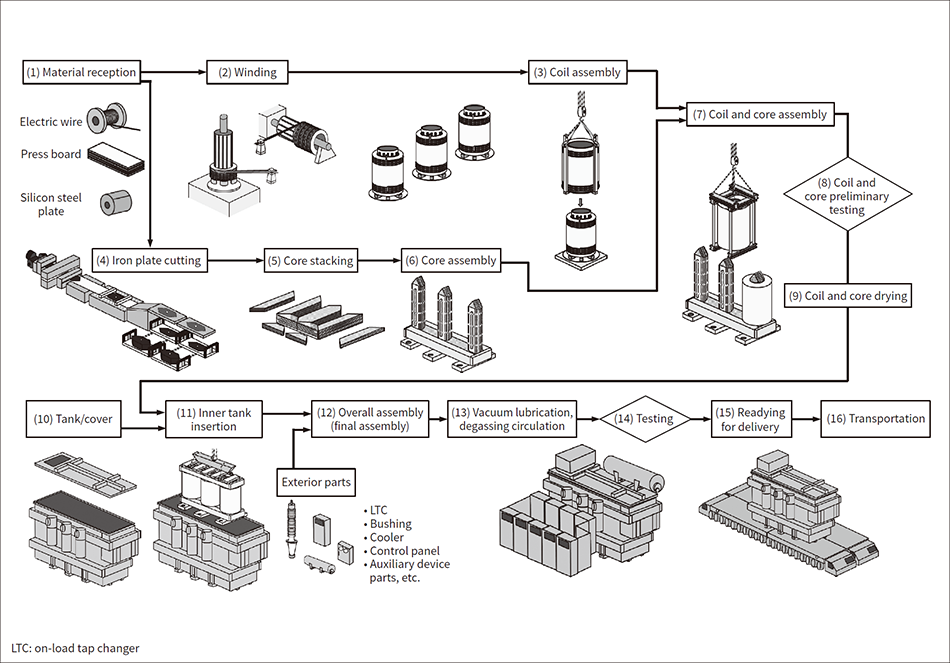 The process for winding, core stacking, core assembly, final assembly, factory testing, and readying for delivery was shortened via measures such as overtime and day and night work shifts.
The transportation of the transformer in this project was performed overland from the Kokubu Factory to Hitachi Port, by sea from Hitachi Port to Onahama Port, and then overland from Onahama Port to Nakoso Power Station (see Figure 4).
Even after removing the exterior parts for transportation, the weight of the transformer in this project was 290 t and the stacked height on the vehicle was more than 9 m, making it extremely large equipment. This meant that mitigation measures were required along the transportation route to protect objects buried underground, avoid overhead obstacles, and reinforce bridges. Because there is no quay wall for unloading from a ship at Nakoso Power Station, mitigation measures were required across a wide range, not only on the public road from the Kokubu Factory to Hitachi Port, but also on the public road from Onahama Port to Nakoso Power Station (see Figure 5).
Furthermore, as the factory shipment date was pushed forward, the mitigation process was shortened, necessitating many negotiations with stakeholders related to the roads, vehicles, ports, shipping lanes, ships, heavy machinery, and other areas used for transportation. Usually, the route from the Kokubu Factory to Hitachi Port can only be used at night on Friday. Hitachi needed to negotiate with local citizens, local government, and the police to obtain special permission to travel the route at night on Thursday. Hitachi arranged the schedule so that the ship loading, sea transportation, and ship unloading, which would normally take three days, could be completed on the same day. This avoided work on Sunday, which is prohibited in principle under local restrictions, for unloading the ship at Onahama Port and the transportation on the public road from Onahama Port to Nakoso Power Station. These actions shortened the time from factory shipment to arrival at the site from the normal five days to three days, which was an unprecedentedly short transportation time.
Figure 4 — Transportation Route from Onahama Port to Temporary Staying Area to Nakoso Power Station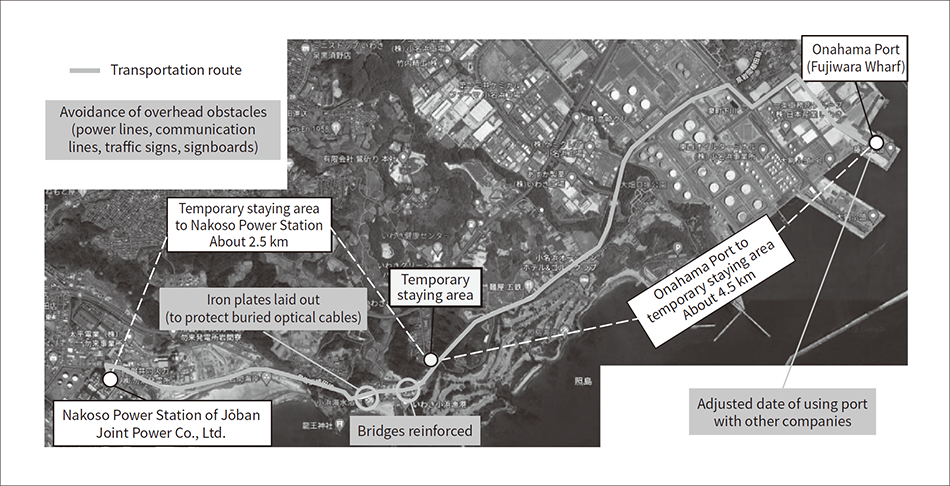 The overall process from factory shipment to arrival on site was performed in the following order: May 19 (Thursday), night-time transport on public road (Hitachi Works Kokubu Factory to Hitachi Port); May 20 (Friday) 6:00 to 9:30, ship loading (Hitachi Port); 9:30 to 12:30, sea transport (Hitachi Port to Onahama Port); 12:30 to 17:30, unloading from ship (Onahama Port); May 21 (Saturday) 3:00 to 6:00, transport on public road (Onahama Port to temporary staying area); 6:00 to 10:00, waiting (temporary staying area); 10:00 to 12:00 transport on public road (temporary staying area to Nakoso Power Station).
Figure 5 — Photographs of Transportation Route from Onahama Port to Temporary Staying Area to Nakoso Power Station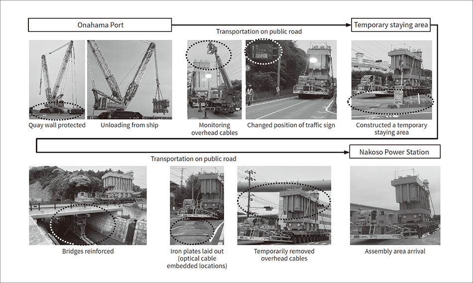 The areas shown in the ovals were the subjects of countermeasures.
Hitachi held repeated discussions with the customer to shorten onsite processes in any way possible, even if only by one day. The process was shortened as much as possible through measures such as improving workability by dismantling the wall of the existing transformer building, and a wrapping process to secure empty space within the power station.
In the installation area, the cable pocket was replaced and the cooler was assembled before the main unit was placed on the base. In parallel, the exterior parts were installed on the main unit in the empty space (assembly area) within the power station, and then the main unit was transported within the site to the installation area, enabling a smooth transition to the next process (see Figure 6).
Furthermore, an onsite system was constructed for work on holidays and in day and night shifts by borrowing personnel from other projects and increasing the number of workers from partner vendors. Other actions included reassigning various workers to meet the shipment date that was pushed forward and coordinating with the customer’s work schedule. This enabled the entire work process from equipment arrival to power transmission to be completed with almost no interruptions.
Normally, system testing is often performed together after finishing the equipment standalone testing. However, in this project, the transformer standalone testing that could be performed on the same day, such as LTC remote operation testing, confirmation of remote display of alarm failures, and current transformer (CT) polarity testing, were performed successively.
The cables used for system testing were laid out in advance between each testing location for a smooth transition to the testing process (see Figure 7).
Initially, there was not a single free day planned after the arrival of the equipment, but by continuing to explore every opportunity to shorten the process, the power transmission process that was scheduled for June 29 could be pushed forward by two days to June 27 due to system testing.
Figure 6 — Photographs of Onsite Assembly and Installation Work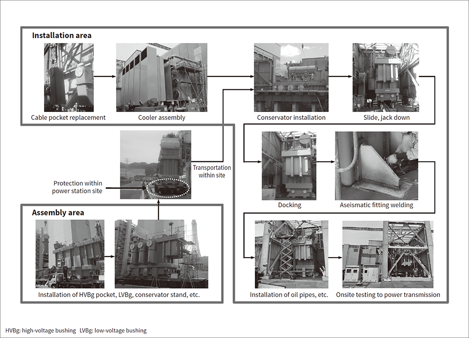 Hitachi devised the shortest possible process by improving workability (dismantling the wall of the existing transformer building), performing work before placing the main unit on base (cable pocket replacement, cooler assembly), and performing a wrapping process using empty space (exterior part installation).
Figure 7 — Diagram of Cable Layout for System Testing at Site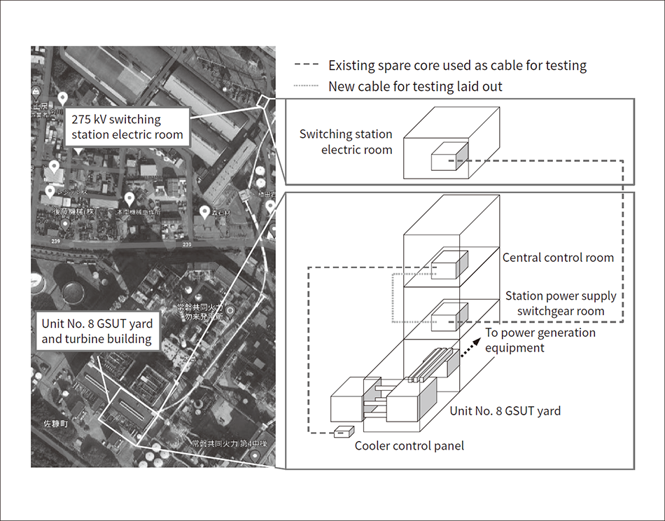 A communication line (2 cores), standard line (2 cores), and matching phase detection line (1 core) were laid out. The results of an advance site investigation showed the need to lay out new cables for testing in sectors with no existing spare cores.
Although the existing design was repeated to achieve the shortest possible delivery time, there were some areas of the 40-year-old design that could not be duplicated. The countermeasures for such areas were reviewed closely by experts as Hitachi made every effort to assure the quality of the new transformer.
Since it was necessary to match the interfaces with the existing cable heads, the dimensions at the site were measured and the structure was changed to one with plenty of allowance for adjustments, such as changing the bolt hole diameters and increasing the number of part divisions.
The results of the investigation into the cause of the failure of the unit No. 8 GSUT showed that a short circuit occurred between taps. This was caused by overheating and damage of the contacts on the LTC main unit tank side, due to aging. About 40 years had elapsed since this transformer had started operations and the number of LTC switches was about 120,000, which is approximately one quarter of the number of switches generally expected. From these facts, it was deduced that the failure was a phenomenon more likely to occur under the conditions of both “significant aging” and a “low LTC switching frequency.” (When surface roughness and level differences between specific contacts progress due to use in a limited tap range and the terminal position remains fixed, overheating occurs more easily due to deterioration of contact energization, carbon adhesion, and other factors.)
As preventive maintenance for the future, in addition to lifting inspections of the changeover switches on the regular maintenance menu, Hitachi added contactor inspections for the LTC segment (tap selection device, polarity switch) on the tank side of the transformer main unit in significantly aged equipment to the maintenance menu.
Figure 8 — Diagram of Induced Voltage Countermeasures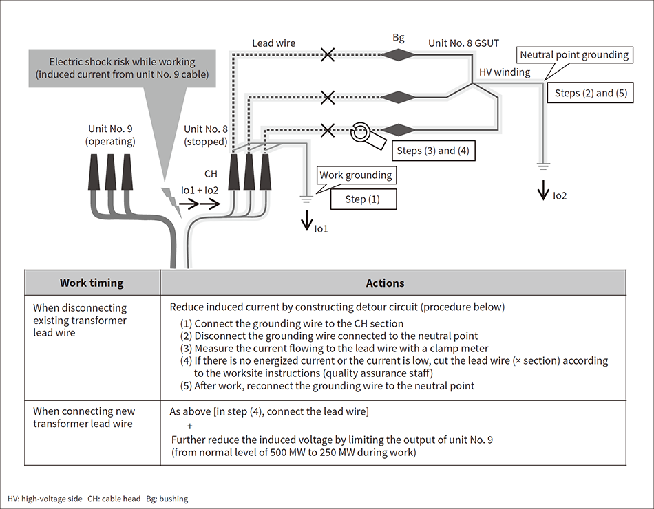 Measures were taken to reduce the induced current when disconnecting and connecting the lead wire between the transformer and cable heads, which reduced the risk of accidental electric shocks and allowed work to proceed.
During the work disconnecting the existing transformer from the cable heads, induced current from the adjacent operating unit No. 9 was observed. As a result, Hitachi considered countermeasures against electric shocks (see Figure 8).
Measures to reduce the induced current were taken by constructing a detour circuit when disconnecting the lead wire between the existing transformer and the cable heads. The results of subsequent verification also confirmed the effect of reducing the induced current by limiting the output of unit No. 9. Therefore, when connecting the lead wire between the new transformer and the cable heads, in addition to constructing the detour circuit, Hitachi asked the customer to limit the output of unit No. 9, which further reduced the induced current and made the work safe.
This project to help solve the social problem of a power supply crunch was an invaluable experience for Hitachi, as it looked beyond conventional frameworks to take the best actions it could, while sharing with the customer information about the risks and opportunities of shortening processes. Hitachi made a significant contribution to power supply stabilization in Japan by rapidly restoring the unit No. 8 GSUT.
In the work on the rapid restoration of the unit No. 8 GSUT at the Nakoso Power Station of Jōban Joint Power Co., Ltd., Hitachi received the support of Jōban Joint Power Co., Ltd. and many other stakeholders. The authors would like to express their deepest gratitude to everyone involved in the project.
