The achievement of carbon neutrality, which involves reducing carbon dioxide emissions to virtually zero as a measure against global warming, is recognized as a challenge facing the entire world. Furthermore, as energy markets are significantly destabilized due to the current international situation, the restarting of nuclear power plants as a means of dealing with these types of problems has become a priority within Japan. To contribute to carbon neutrality and the stable supply of electric power, Hitachi is strengthening its efforts towards restarting nuclear power plants while working to supply nuclear power systems that comply with new regulatory standards that offer the highest level of safety in the world. This article discusses Hitachi’s efforts towards enhancing the safety of nuclear power plants before they are restarted, as well as the safety measures and construction technologies Hitachi is implementing to achieve the actual restart.

As the international movement towards decarbonation proceeds with a goal of carbon neutrality, while energy markets are destabilized by Russia’s invasion of Ukraine, the restarting of nuclear power plants within Japan that can contribute to the achievement of a stable supply of electricity along with carbon neutrality has become a vital domestic issue as well.
Based on the lessons learned after the Fukushima Daiichi Nuclear Power Station accident, Hitachi has formulated a basic policy for boiling water reactor (BWR) plant safety measures while promoting the development of safety enhancement technology to further increase the margin of safety at nuclear power plants.(1), (2) At present, to successfully restart nuclear power plants, Hitachi is supporting compliance inspections based on new regulatory standards and conducted by electric power utilities, while promoting the adoption of safety equipment by nuclear power plants.
This article describes the safety measures Hitachi has worked to develop to facilitate the restarting of nuclear power plants, as well as the safety measures and construction technologies used to quickly implement safety equipment.
This section provides an overview of the design basis accident response equipment and major accident response equipment Hitachi is promoting deployment of to further improve margins of safety at nuclear power plants, which will enable them to comply with the regulatory standards necessary for restarting nuclear power plants.
In addition to the development and design of this equipment, Hitachi also uses analytical techniques such as accident progress analysis to evaluate effectiveness and confirm that the equipment can function in such a way as to maintain safety even during an accident.
Table 1 — Strengthening Design Basis Accident Response Equipment The following measures are aimed at securing safety in the event of a major design basis event (earthquake, internal fire, or internal overflow).
Table 2 — Overview of Equipment for Responding to Incidents Such as Major Accidents This table lists the major safety equipment that should be introduced in the event of a major accident or similar incident to prevent major core damage and containment vessel damage, and to suppress the emission of radioactive substances.
This section provides the details of the safety enhancement technology that Hitachi is applying in its safety equipment.
Figure 1 — Schematic Diagram of Molten Debris Cooling Equipment (Floor Construction System)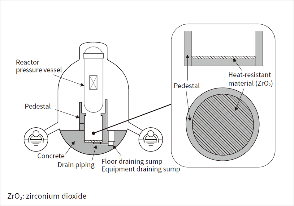 The containment vessel boundary is protected from molten debris through the adoption of heat-resistant material (ZrO2) combined with the use of water injection equipment in the lower part of the containment vessel.
Figure 2 — Passive Autocatalytic Recombiner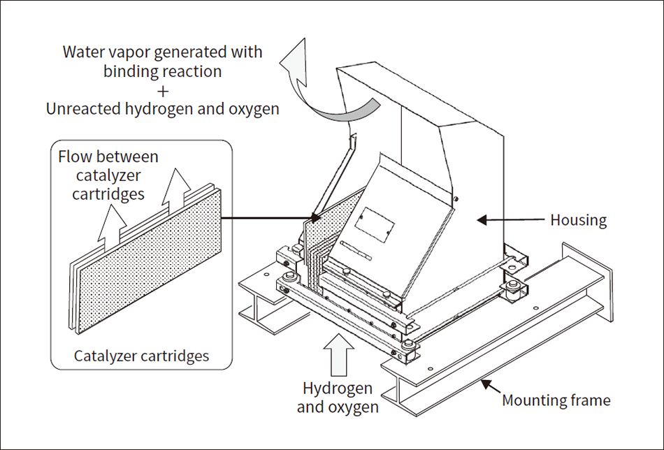 A passive autocatalytic recombiner (PAR) is comprised of a housing and catalyzer cartridges, and causes a binding reaction in the combustible gas (hydrogen and oxygen) that flows in from the bottom due to natural circulation using each catalyzer cartridge’s catalyzer (palladium) layer, in a structure that causes the resulting water vapor to be emitted from a port at the top.
Figure 3 — Vibration Test of Side-opening BOP Closing Device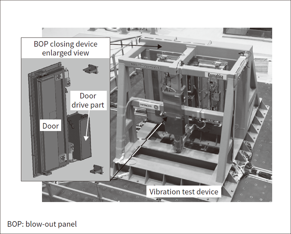 Retention of earthquake proof functionality was confirmed using a full-scale vibration test set with vibrating conditions far in excess of those that occurred during the Great East Japan Earthquake.
This section describes Hitachi’s efforts towards streamlining the construction of safety measures utilizing three-dimensional (3D) laser measurement technology that it is developing as a means of quickly introducing large-scale safety equipment into nuclear power plants.
Hitachi is utilizing point cloud data acquired using 3D laser measurement technology as part of nuclear power plant engineering, procurement, and construction (EPC) work to measure dimensions, produce three-dimensional computer-aided design (3D-CAD) data, and create working drawings for purposes such as constructing a new piping route onsite. To this end, Hitachi also developed a point cloud access tool to serve as infrastructure for the cross-sectional sharing of point cloud data between design departments. These tools manage multiple point cloud data formats on a centralized server while supporting the diverse usage patterns of different users with dedicated viewers and functions that link with external tools. Also, to enable users to utilize large amounts of point cloud data, the tools achieve faster processing through techniques that cull data, leaving valid data behind, and also enhance the interface. Figure 4 shows the process for utilizing point cloud data using 3D laser measurement technology, and Table 3 provides examples of how to utilize the data.
Figure 4 — Process for Utilizing Point Cloud Data from 3D Laser Measurement Technology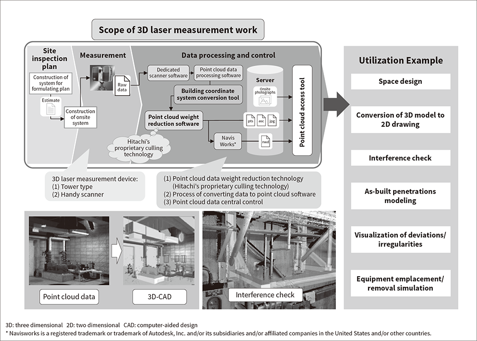 By utilizing 3D laser measurement technology to collect point cloud data onsite and managing it with dedicated tools, not only is it possible to apply the technology to design work, but applications can also be expanded to construction planning and other tasks as well.
Table 3 — Examples of Utilizing 3D Laser Measurement Data It is possible to utilize onsite information as point cloud data for use in a variety of different design and construction tasks.
As part of the process of preparing to restart nuclear power plants, Hitachi is proceeding with the installation of the various types of safety equipment described in the previous section in actual plants. During this safety measure construction period, it is also necessary to conduct a wide range of different conversion work in parallel, including the piping of equipment within the nuclear power plant, air conditioning, electricity, instrumentation, seismic strengthening, fireproofing, and so on. Temporary equipment used in the conversion work such as scaffolding, material storage areas, temporary power supplies, and welding machines are also arranged around the inside of the power plant, and the layout information for locations of related equipment changes every day while construction proceeds.
To conduct this safety measure construction work safely and smoothly, it is extremely important to check for interference and plan routes according to the state of the power plant equipment so as to identify equipment that may interfere with the equipment delivery route and to formulate plans to avoid interference. Not only does this make it possible to smoothly transport equipment both in and out of the plant, but also to prevent damage to existing and newly delivered equipment due to collisions during movement.
This section introduces a study on the streamlining of a construction plan utilizing 3D laser measurement technology, based on the concrete example of an interference confirmation and routing plan for equipment loading/unloading as part of the installation of new panels.
The following six tasks must be performed to formulate an interference confirmation and routing plan before panel update construction can begin.
Since these tasks are greatly affected by backtracking work caused by situations such as when a site cannot be investigated due to other conversion work or the power plant operation plan, or by delayed confirmation of whether or not interference can be avoided, they entail a risk of drawing out the construction process. Also, since onsite inspections are mandatory, there are risks such as radiation exposure during inspections of controlled areas and construction accidents during onsite inspections.
Utilizing point cloud data from 3D laser measurement technology here enables advanced information control, and is thought to help streamline the interference confirmation and routing plan as shown in Table 4 by shortening schedules while improving work safety. At present, the application of 3D laser measurement technology is still in the demonstration and experimentation stage, and its effectiveness as a utilized technology is being confirmed. Hitachi plans to incorporate 3D laser measurements into actual work on a trial basis in the future, and to promote further efforts towards the streamlining of safety measure construction work.
Table 4 — Effectiveness of 3D Laser Measurement Technology Expected effects include shortening of work schedules, advanced information management, and improvements in work safety.
The restart of nuclear power plants is an extremely important option for securing a stable domestic supply of electric power while achieving a decarbonized society. Not only does the technology introduced in this article comply with the regulatory standards of nuclear power plants, but it can also greatly contribute to the enhancement of safety and shows promise as a way of safely and smoothly constructing safety measures.
Hitachi will continue to contribute to ensuring a stable supply of electricity and achieving carbon neutrality through its efforts to restart nuclear power plants.
