In recent years, the decommissioning of nuclear power plants has been accelerating in Japan. Although it is necessary to shred the metal waste resulting from dismantling machinery onsite depending on the inspection and disposal method used after dismantling, from the perspectives of preventing fire and preventing contaminants from dissolving into steels, it is strongly preferred to apply a cutting method such saw blades that do not use fire. Based on this, Hitachi Plant Construction, Ltd. utilizes machinery it developed in-house to deploy fire-free equipment cutting solutions, and is contributing to safe operations and the proper disposal of waste, which are issues involved in the execution of decommissioning. This article describes Hitachi Plant Construction’s track record in this area, introducing techniques such as shredding large equipment onsite with a bandsaw and removing contamination from steel surfaces by milling. It also provides an overview of technology under development based on future trends in decommissioning.


Of the 57 commercial nuclear power plants that currently exist in Japan, 18 are undergoing decommissioning(1), (2). Decommissioning refers to the dismantling and removal of equipment and buildings from a power plant that has ceased operations, while clearing away radioactive substances. Power companies that perform decommissioning work must safely execute a plan approved by the national government over a period of approximately 30 years, and depending on the state of contamination by radioactive substances, must properly dispose of wastes.
In general, decommissioning work starts with the dismantling and removal of (1) peripheral equipment from areas of the nuclear reactor with no contamination or comparatively little contamination (turbines, generators, steam condensers, etc.), continues with (2) equipment from areas of the nuclear reactor with comparatively greater levels of contamination (reactor pressure vessel, internal equipment from the vessel, etc.) and finally ends with (3) buildings and other such objects. Domestic reactors that are leading in the decommissioning process are currently in stage (1) in terms of the dismantling of peripheral equipment from areas of the nuclear reactor.
When it comes to the metal waste generated by this decommissioning, it is necessary to shred onsite to a size that is suitable based on the inspection and disposal methods established according to the level of contamination. While the use of fire, such as gas cutting, enables relatively efficient shredding to the desired size and shape, the risk of fire increases, and radioactive substances adhering to the surface of the material to be shredded cannot be removed if they are incorporated into the cut section, so fire-free cutting methods such as using saw blades, etc. are strongly desired.
It is against this background that Hitachi Plant Construction, Ltd. utilizes equipment such as a large, field-assembly-type bandsaw that it has developed in-house in deploying fire-free equipment cutting solutions, thereby contributing to the resolution of issues in decommissioning execution including operational safety and proper waste disposal. This article introduces Hitachi Plant Construction’s track record in this area, and provides an overview of the technology under development based on future trends in decommissioning.
The large bandsaws that are one of the core types of technologies possessed by Hitachi Plant Construction can be used for fire-free cutting onsite without the need to transfer power generation turbines or other large objects to a dedicated facility. The company has a track record of more than 25 years of applying this technology for equipment removal and other projects at hydro-power, thermal power, and nuclear power plants, and has a lineup of models tailored for cutting objects of different sizes and shapes or installation locations, combined with a wealth of accumulated cutting data and know-how. Situations for utilizing these capabilities have increased in recent years, such as for decommissioning projects at nuclear power plants, and the company receives inquiries regarding solutions for a variety of different challenges from customers that need help with fire-free equipment cutting solutions. The next section will discuss bandsaws, followed by an introduction to one example of a new fire-free cutting technique that Hitachi Plant Construction came up with through co-creation with a customer.
A bandsaw is an electric tool that rotates a loop-shaped saw blade in order to cut wood, metal, and other objects. There are a wide variety of different types of bandsaws depending on the application, from small versions that can be held in the hand to large stationary machines that are installed in factories.
Figure 1 shows a schematic diagram of the basic structure of Hitachi Plant Construction’s bandsaws. The saw blade is attached to wheels arranged on the left and right side of the frame and held there with a constant level of tension. The wheel on the right side of the diagram is rotated with a motor to cause the saw blade to move over an orbital path. It is also possible to raise or lower the left and right wheels using a linear motion mechanism called a vertical jack. Lowering the orbiting saw blade with this type of machine configuration can vertically cut the object affixed between the wheels in two places at the same time.
Figure 2 shows a photograph and specifications for Hitachi Plant Construction’s main lineup of bandsaws. The main attribute common to all models in the company’s lineup is a structure that lets the frame and all parts of the mechanism be dismantled, assembled, and transported, so that it is possible to cut target equipment wherever it is installed. This makes the bandsaws particularly effective for dismantling and removing large equipment that cannot be transported as-is away from where it is installed due to mass and size restrictions. Also, in recent years machines have incorporated vibration sensors or laser displacement gauges to convert operating conditions to data, and efforts are being carried out to utilize this information to help make judgements regarding cuts without the need to rely on the five senses of skilled operators, or to automate cutting.
Figure 1 — Basic Structure of Hitachi Plant Construction’s Bandsaw The bandsaw vertically cuts the target object by causing a saw blade on the left and right wheels to move from top to bottom while orbiting.
Figure 2 — Hitachi Plant Construction Bandsaw Lineup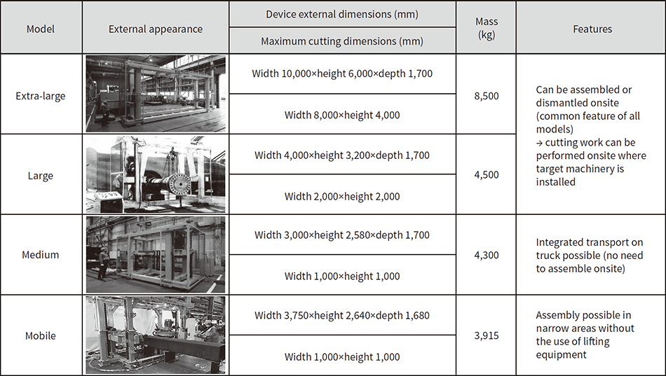 The structure of the frame and various parts of the mechanism allows for dismantling, assembly, and transport. This main feature means that the bandsaw can be used to cut target machine onsite where it is installed.
Figure 3 — Cutting of Board Surface with Face Milling Tool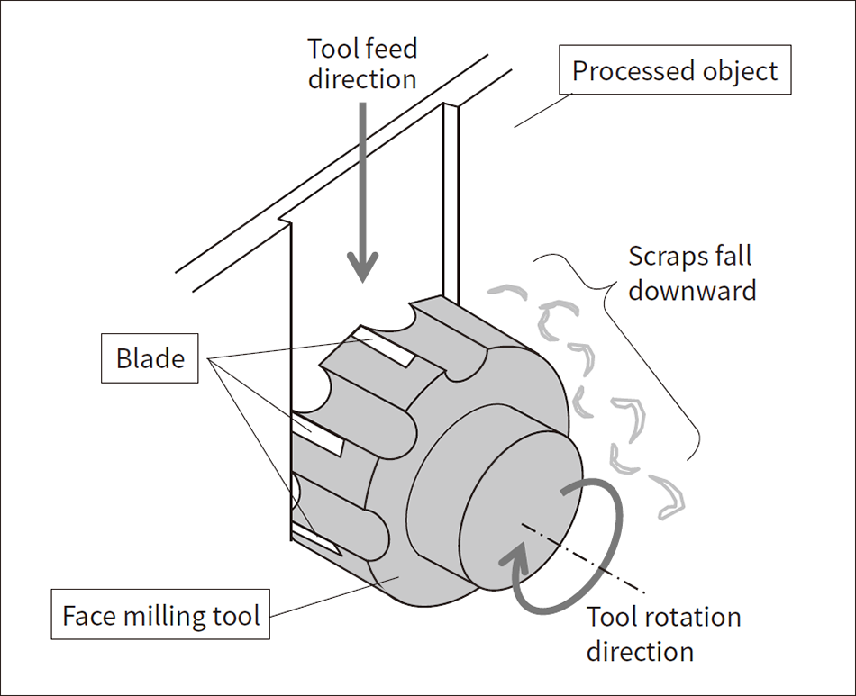 Suitable for efficiently scraping wide surfaces, and always produces scraps from scraped areas. Also, moving the tool from top to bottom causes the scraps to fall due to their own weight.
A nuclear power plant’s exhaust stack is designed to release gaseous radioactive substances at a sufficiently safe level to ventilate the building and to generate during operation(3).
Hitachi Plant Construction received an inquiry from Chubu Electric Power Co., Inc. asking for a proposal of a new fire-free method to assist with the disposal of a dismantled steel exhaust stack, with a height of 100 m and a maximum diameter of 8 m, from a reactor at a plant currently undergoing decommissioning so that the stack itself could be widely utilized by society as nonradioactive industrial waste. The conditions for the work were as follows:
Company engineers who had participated in the development or operation of fire-free cutting equipment considered these conditions and proposed equipment and techniques using the “face milling tool,” which is one type of rotary cutting tool.
Figure 3 shows this face milling tool along with an image of the steel surface being cut. The face milling tool has multiple blades arranged around its circumference, and proceeds by shaving off a flat plane that is the diameter of the tool while sending the milling cutter or target object in a direction at a right angle to the axis of rotation. This tool is suited for efficiently scraping at a wide flat plane, and always generates scraps from the scraped locations, while preventing scraps from adhering to the processed surface as they fall due to their own weight as the tool is moved from top to bottom as shown in the diagram. Since the features described above comply with the technique’s requirements, Hitachi Plant Construction developed “equipment for removing contamination from steel surfaces” using this face milling tool.
The structure of this contamination removal equipment is shown as a schematic diagram in Figure 4. The device is comprised of a milling cutter part and a cutting table. The milling cutter is comprised of a main shaft that rotates the tool with a 15-kW motor, an electric linear motion mechanism for raising and lowering the main shaft, and an electric linear motion mechanism that adjusts the depth of cuts in the direction of the thick steel plate. The main shaft’s rotational frequency is 300 min−1, the diameter of the attached tool is 125 mm, and this tool can be swapped out with another tool of a different diameter if necessary. The speed at which the main shaft rises and falls was set to a maximum of 500 mm/minute to meet the customer’s requirements for a processing speed of 300 mm/minute for the entire process. To ensure that scraps would definitely be formed from the cuts to the surface, it was decided to set the depth of cutting in the direction of the plate thickness to around 1 mm.
Based on a consideration of ease of use during transport within a site and other such issues, the cutting table side was configured with a surface plate that fixes the shredded pieces of the exhaust stack in a vertical orientation after they are segmented in advance with a height of around 1 m and a width of around 1.5 m. This surface plate has electronic linear motion mechanisms that can move in two axes with respect to the milling cutter, namely, forward/backward and left/right. Furthermore, it has a turning mechanism around the vertical axis to position the shredded pieces from the curved exhaust stack to face towards the milling cutter.
Figure 5 shows the results of the process for using this device to remove the steel surface. Figure 5 (a) is a photograph of recovered shreds. Shreds were obtained in a characteristic arc shape after the metal was cut, making it possible to confirm that the steel surface was definitely removed. Also, as described previously the processing direction was always facing downward, and a cover was attached to prevent the scattering of shreds around the equipment, with compressed air blown over the tool to prevent the adherence of shreds. Figure 5 (b) and (c) show pieces of the actual exhaust stack before and after the removal process. The customer’s requested work schedule was met, and up to a maximum of 500 mm/minute of the surface of the exhaust stack was cut while using φ100, 125, and 160 mm tools depending on the radius of curvature and the state of the surface.
Figure 4 — Equipment for Removing Contamination from Steel Surfaces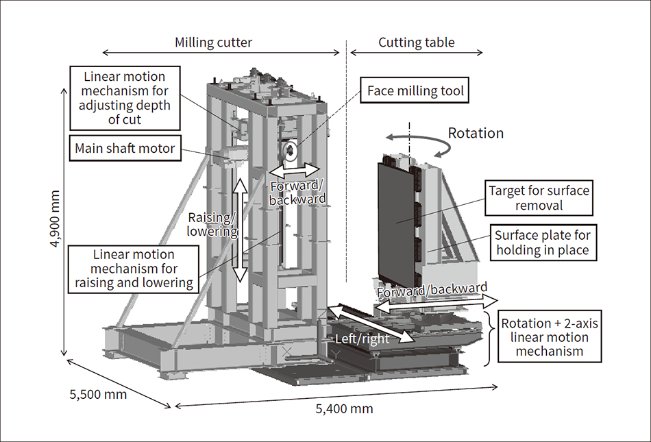 This equipment is comprised of a milling cutter and a cutting table. The milling cutter includes a 15-kW motor that rotates the tool around the main shaft, and an electronic linear motion mechanism that raises and lowers the main shaft, and an electronic linear motion mechanism that adjusts the depth of cutting in the direction of the thick steel plate. The cutting table side includes a surface plate for holding the shredded piece of the exhaust stack in the vertical direction, two shafts with electronic linear motion mechanisms for moving the surface plate forward/backward and left/right with respect to the milling cutter, and a rotating mechanism that moves the curved exhaust stack shredded piece around a vertical shaft to face towards the milling cutter.
Figure 5 — Removal of Steel Surface with the Equipment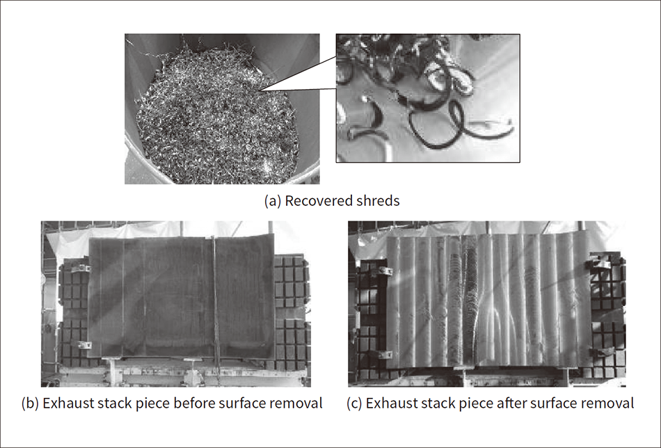 As shown in (a), the characteristically arc-shaped shreds created by cutting the metal are produced, and it is confirmed that they are reliably “removed” from the steel surface.
Figure 6 — Overview of Remote Robot Operation System under Development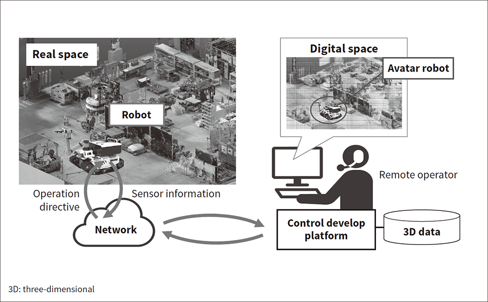 The operator pilots an avatar robot that moves in exactly the same way as the actual robot based on various types of sensor information in a faithful reproduction of the site in a digital space. Since the blind spots of conventional cameras are eliminated, complex operations can be performed easily, safely, and reliably while visually confirming operation from any viewpoint.
The previous section introduced one example of a fire-free equipment cutting solution for decommissioning of a nuclear power plant by shredding a large structure using Hitachi Plant Construction’s conventional bandsaw technology, as well as a new technique, developed through co-creation with a customer, for removing the contamination from a metal surface using a milling cutter. The company works to satisfy customer needs for onsite decommissioning in this way while at the same time conducting research and development to anticipate the new needs of the future. One key concept is “transitioning to remote operation.”
Plants leading the way with their decommissioning work are planning to start dismantling operations in the nuclear reactor area soon. The need for fire-free cutting will likely remain high, and it will be necessary to take countermeasures to reduce the exposure of workers during this dismantling work due to the comparatively high level of contamination. Therefore, the company is developing a waterproof bandsaw for use underwater to take advantage of the ability of water to shield from radiation.
In this environment, it is also desirable, as much as possible, to do this equipment shredding and other dismantling work remotely. Hitachi Plant Construction is currently collaborating with a customer, which is seeking to decommission next-generation reactor, to develop a robot system for decommissioning that applies digital twin technology. Although the conventional method of remotely operating this type of robot involved viewing images from a camera installed on the equipment itself or onsite, it was difficult for the operator to accurately and intuitively judge whether or not the robot was operating correctly just from a flat camera image.
Figure 6 illustrates the concept of Hitachi Plant Construction’s robot system. With this system, instead of the operator controlling a robot viewed with a camera, the operator pilots an avatar robot that performs the exact same motions as the actual robot, based on various types of built-in sensor information, by faithfully reproducing the site using laser scanner measuring instruments and three-dimensional computer aided design (3D-CAD). This eliminates the blind spots of conventional camera systems, making it possible to easily, safely, and reliably perform complex operations such as moving through a narrow and complicated set of passages, avoid obstacles in front of it, and grabbing objects at the end of the passages with a manipulator while viewing them from a free viewpoint.
Hitachi Plant Construction has accumulated more than 25 years of experience and knowledge regarding the cutting of various objects onsite with bandsaws and other machinery it has developed in-house. In the future, the company will combine new forms of information (digital) technology (IT) with operational technology (OT) to collaborate with customers on the creation of new IT and OT solutions, while contributing to the realization of a carbon-neutral society with the proper disposal of waste using fire-free cutting methods.
