22 October 2021

Xiaoliang Zhu
R&D Division, Hitachi America, Ltd.

Subrata Kumar Kundu
R&D Division, Hitachi America, Ltd.
In the last ten years, advances in sensing, communication, and control technologies have rapidly led the automotive industry into the fields of connected vehicles and autonomous vehicles to improve driving safety, comfort, efficiency as well as to reduce emissions. In these fields, the suspension system which reduces or eliminates vibrations transmitted to the vehicle body, is a key mechanical component in improving driving comfort. A recent market trend report [1] projects that the global automotive suspension market will grow from USD 42.9 billion and reach USD 50.7 billion in 2026 with a compound annual growth rate (CAGR) of 3.4%, due to the increasing demand on ride comfort and handling.
Automotive suspension systems can be classified as passive, semi-active, or active systems, based on their ability to dissipate, add or extract energy. Figure 1 shows the cross-sectional view of a commonly used suspension strut under free load and maximum load. During operation, the piston rod is forced to move reciprocally by vibrations or bumps on the road, moving hydraulic oil between different chambers in the absorber and converting the vibration energy into heat which is then dissipated. During the piston rod’s reciprocal movement, defects on its surface, e.g. nodule, dents, and scratches, will quickly damage the hydraulic oil seal and cause oil leakage, noise, and eventually lead to suspension system failure. Thus, it is critical to inspect the piston rod surface quality before assembling to ensure its durability.
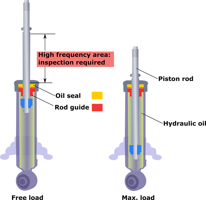
Figure 1. Cross-sectional view of a suspension strut under free load and maximum load
Traditional ways to inspect piston rod surface involved either manual inspection (e.g., eyeballing) or the use of non-destructive online sensors [2-4]. These methods, however, cannot be effectively applied in piston rod inspection due to the wide variety of defects, small defects size, environment noise, and short cycle time.
To address this issue, the Automotive Products Research Laboratory (APL) of Hitachi America, Ltd. R&D has developed an online automatic vision-based piston rod inspection system [5] using convolutional neural networks (CNNs) which allow the inspection of the whole rod surface in 4 seconds, with a detection accuracy greater than 90%.
Figure 2 (a) shows the schematic diagram of the system architecture which consists of an LED light to illuminate the rod surface; a robotic manipulation station for the rod rotation; a line-scan camera to capture the whole rod surface image; and a processing unit to execute algorithms designed to coordinate the robotic manipulation stage and the camera to capture images, and to control the light indicator.
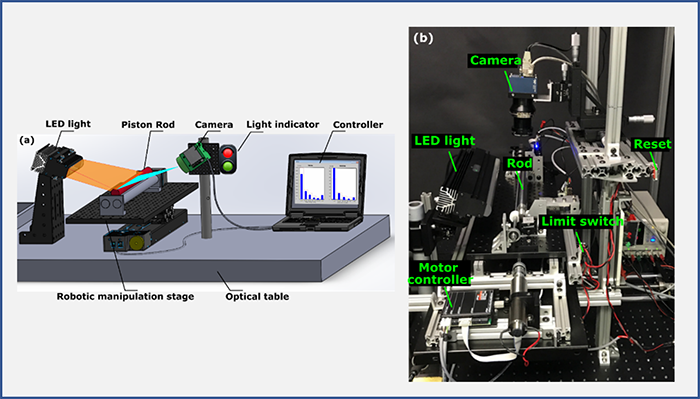
Figure 2. Automatic vision-based piston rod inspection system developed: (a) schematic diagram and (b) experimental setup
Figure 3 illustrates the flowchart of the integrated software from detection of the presence of the piston rod, motor and camera coordination, image processing, to inspection results indication. We applied CNNs instead of classical image processing methods to mitigate the challenges raised by vibrations from other machines, changes in ambient light, or uneven illumination, etc.
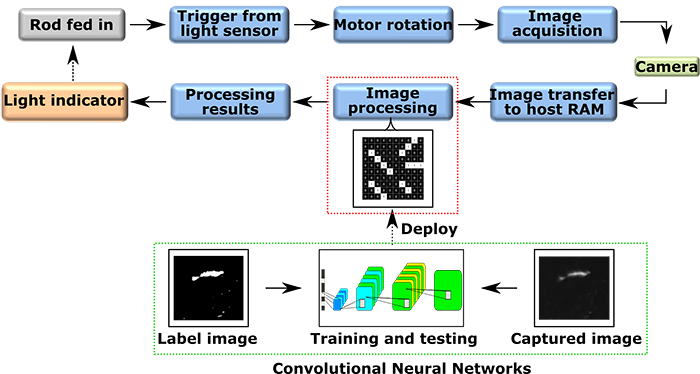
Figure 3. Flowchart of integrated software
To determine the best CNN architecture for the inspection system, images were captured from different piston rods with defects of nodule, dent, and scratch. 342 images with a resolution of 4096 × 262 pixels were used to train the CNNs. (Details of the CNN training and testing information can be found in our publication [5].) Utilizing the captured images, the CNN structure with the best detection accuracy was determined and implemented into the image processing pipeline as shown in Figure 4. It should be noted that defect aspect ratio and size information were used to classify defects of dent, nodule, and scratch, e.g., defects with an aspect ratio greater than 2 is considered a scratch, and diameter information was used to differentiate dent and nodule which have an aspect ratio equal to or less than 2.

Figure 4. Flowchart illustrating image processing steps
Figure 5 shows a sample inspection result, where (a) is the image captured from the camera, which is cropped from a 4096 × 262 frame to show the details clearly; (b) shows the processed image with labelling, where green rectangles are the detected nodules, blue rectangles are the detected dents, and red rectangles are the detected scratches.
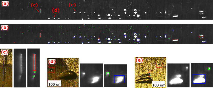
Figure 5. (a) captured raw image of a rod. (b) image after processing and labelling. (c) microscope image of a scratch with 30 µm width and 780 µm length. (d) microscope image of a 30 µm nodule (in red dashed rectangle) and a dent. (e) microscope image of a 25 µm nodule (in red dashed rectangle) and two dents
The corresponding microscope images, the captured image, and the labelled image of defects (c), (d), and (e) are also shown in Figure 5. The inspection results demonstrated that the current inspection system can effectively detect nodules as small as 25 µm and can differentiate nodules, dents, and scratches with a detection accuracy greater than 90% and sizing accuracy greater than 75%. It should be noted that using a higher resolution camera e.g., a 16K resolution camera, instead of the 4K camera used in this study will provide higher sensitivity.
With a processing time around 4 seconds per rod, high accuracy and sensitivity, the automatic piston rod surface inspection system that we developed can be utilized in real production environment to ensure the quality of the suspension component to maximize user riding experience for safety, comfort, carbon emission, and energy efficiency.
For more detail, we invite you to read the original paper [5] which was presented at ICMMM Sep. 2020.
